Project Description
NASA JPL Co-op
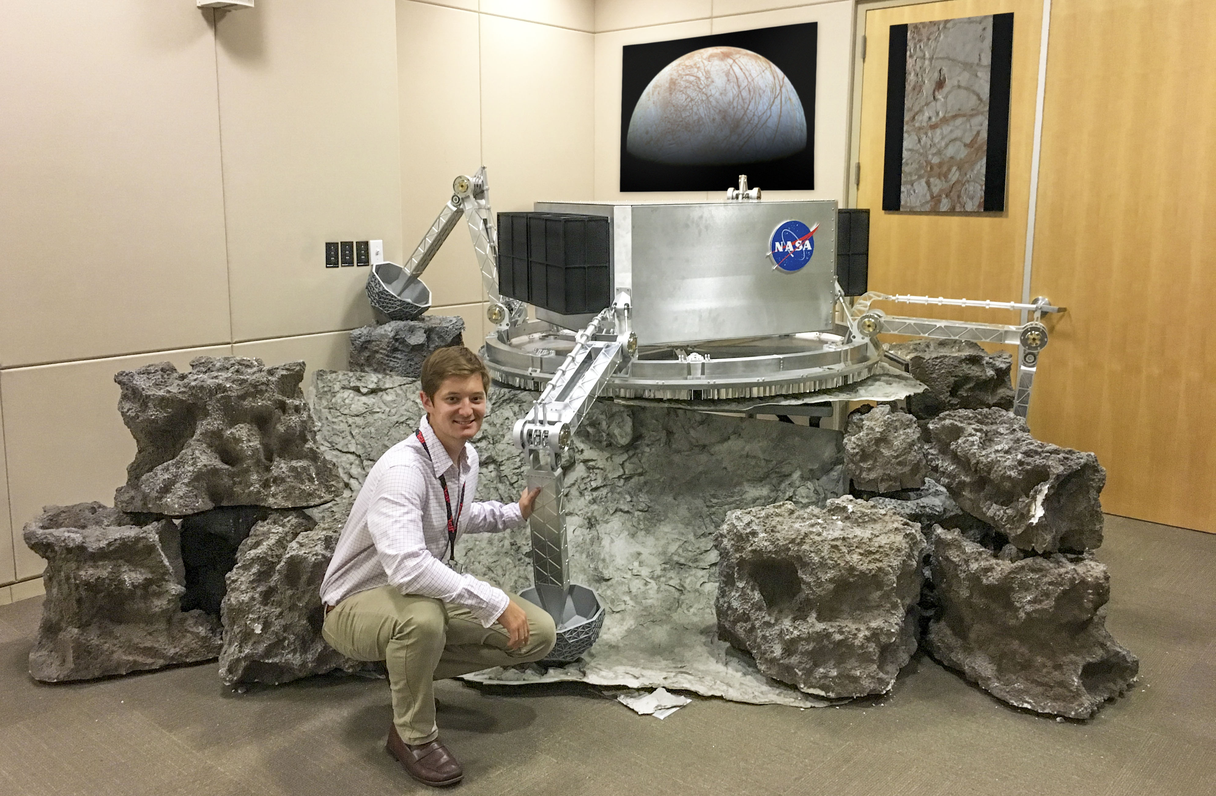
Europa Lander mechanical landing system prototype at the Mission Concept Review.
NASA Jet Propulsion Laboratory was my second six month Co-op. This took me to sunny Pasadena California. I worked in the Spacecraft Mechanical Engineering section within the Entry, Descent, and Landing group on the Europa Lander Mission. This was an early stage project so the team I worked on was very small and my work had a large impact. My main focus was to design, build, and test the first prototype of the landing system. I couldn’t have asked for a better project to work on because I got a lot of both design and hands-on experience all in one Co-op. I also got to carry my prototype all the way to completion. A key take-aways from my experience here was through working on such a specific project with a deadline, I learned how important it is to frequently take a step back from the details and look on a larger scope to make sure you’re staying on schedule. This was also my first time working at such a large organization, so I learned quickly how to navigate through co-workers, managers, and sections to get things done. Lastly, this was also my first time working in the aerospace industry, so I was able to absorb bundles of information on standard design practices, product life cycles, and just general know-how involved in producing spacecraft.
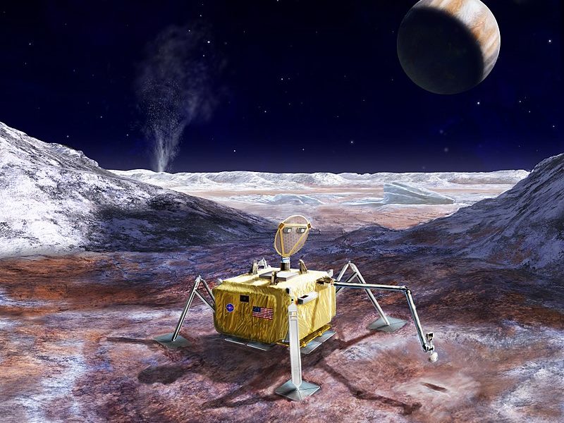
Europa Lander concept state at the start of my co-op.

Functional Europa Lander prototype as result of my Co-op.

Design state at start of Co-op
At the start of my Co-op I was presented with the CAD assembly of the landing system shown to the right. With this as a base line, I had to design a real-world functioning landing system that could be manufactured, assembled, and presented at the Delta Mission Concept Review three months away. I worked with my manager and one other engineer on this project. I was also the only person on-site on my team at JPL during a majority of the design and build phases, so I was responsible for physically getting the prototype built.
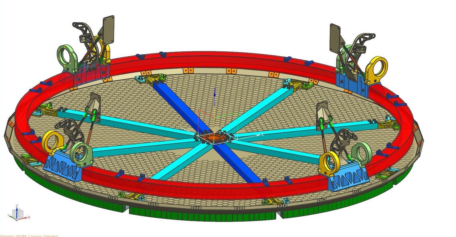
My completed strong back CAD assembly.

Strong back integrated into top-level assembly
I owned the strong back/belly pan assembly design showed above to the left. I designed the belly pan as two sheet metal half circles with tabs around the radius that were bent up to form a rim around the perimeter. I had never done sheet metal design, so it was a great learning experience figuring out how to make this manufacturable and getting the geometries of the seam brackets correct. It was also a challenge designing the leg/strong back interfacing hardware to achieve the correct geometries while also still be manufacturable by Protolabs online and the shop in-house. Protolabs had a relatively small build area and their operations were limited to only 3-axis and small depths. Because of this some parts that started as one needed to be broken up into multiple. I also had an off-axis operation that couldn’t be avoided, so I had that final operation done in-house on a 5-axis machine.

Sarrus Link 1 DOF mechanism.
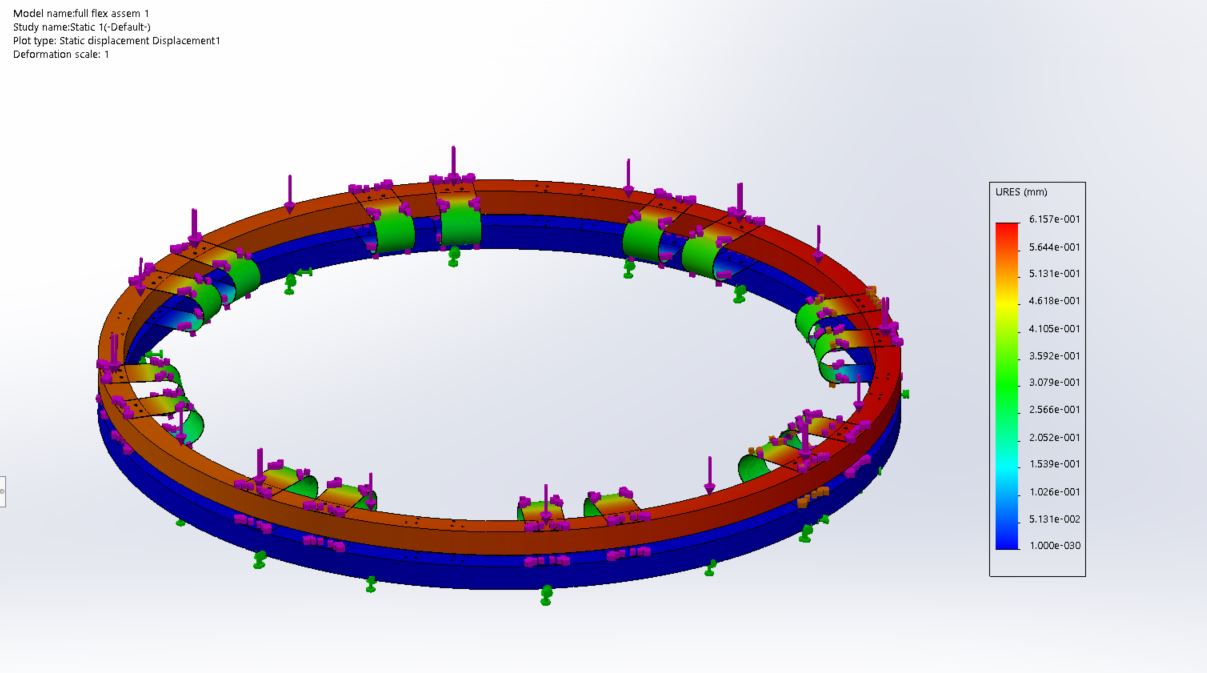
Flexure 1 DOF mechanism loaded on the z-axis in Solidworks FEA.
Another design challenge was that the belly pan needed to be restricted to one degree of freedom in the z-axis. I originally designed a Sarrus linkage 1 DOF mechanism but it was ruled out because it decided to be prone to binding if the linkage members started deflecting under off-axis loading. With that in mind, I designed a simple flexure that I thought would exhibit close to 1 DOF behavior. After some FEA though, it was shown to be unsuccessful.
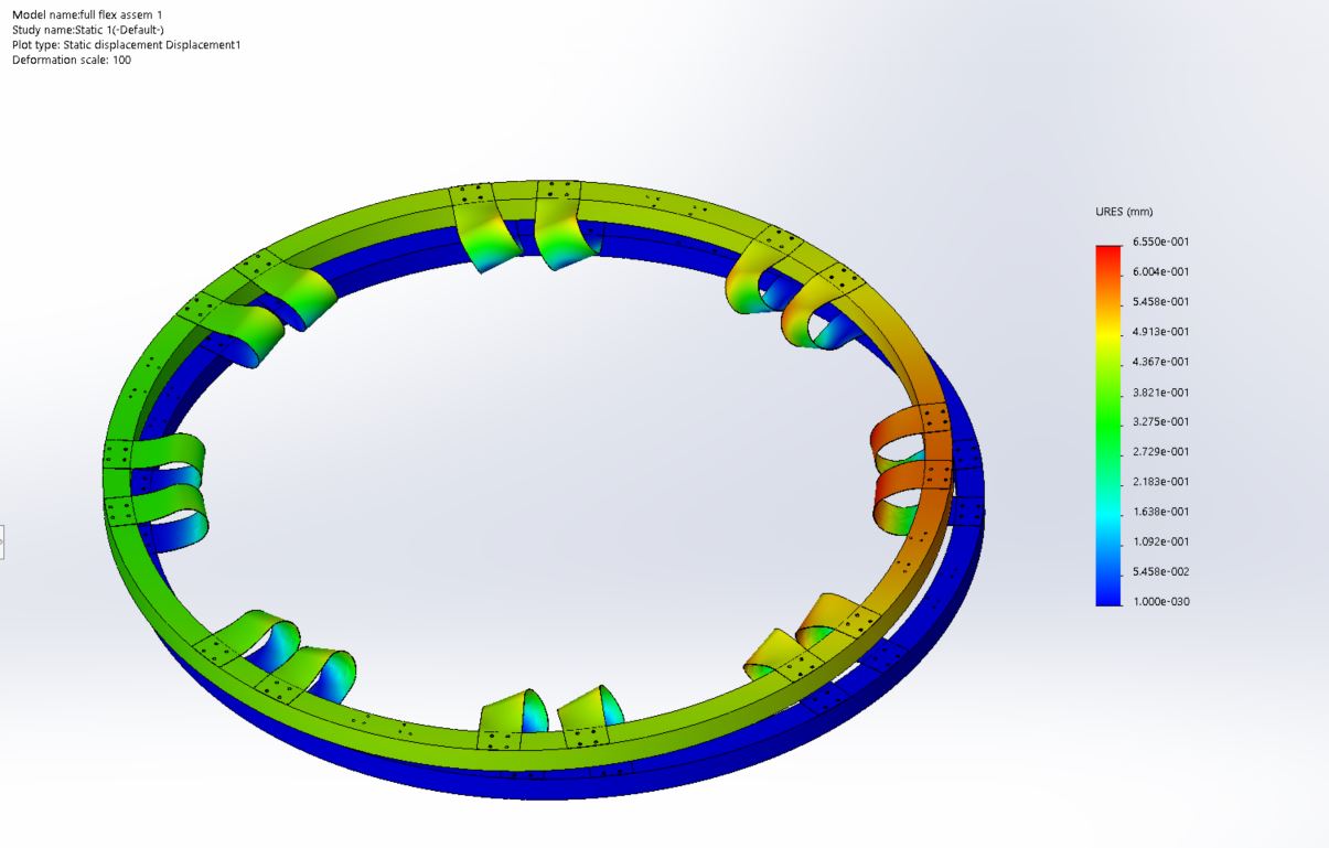
Flexure is clearly does not exhibit DOF behavior when loaded on the x-y plane.
Later, my team member found a 1 DOF mechanism design that was much better for this application called a Hoekens mechanism. This was essentially a four-bar link and with the correct ratio of link lengths, the end node travelled linearly over a short range. The mechanism would react loads much more axially through the linkages than the Sarrus so it was more desirable from an anti-binding stand. Also, from a packaging stand, it was much easier to interface with the strong back. This is shown below to the left.

Hoekens 1 DOF mechanism.
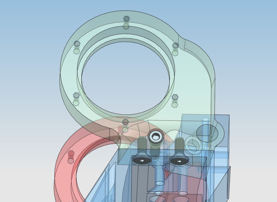
Hip block and leg-locking mechanism interface split into two.
I was responsible for designing everything between the stabilizers (legs) and the vault. So this included the strong back, belly pan, bipods, and leg interfaces. My finished assembly is shown above to the left, and it integrated with my teams assemblies as shown above to the left.
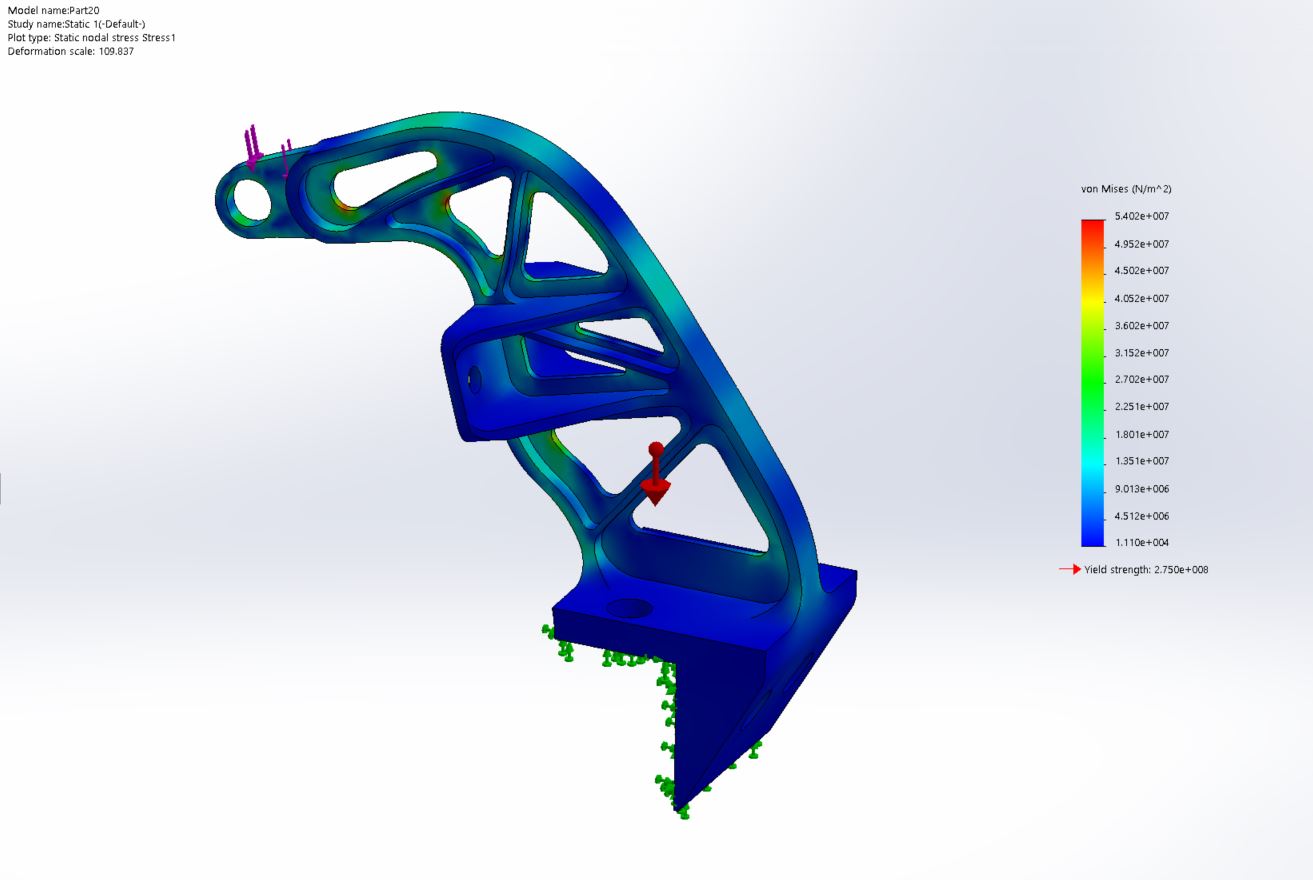
FEA on “compliant anchor” confirmed a 3x factor of safety.
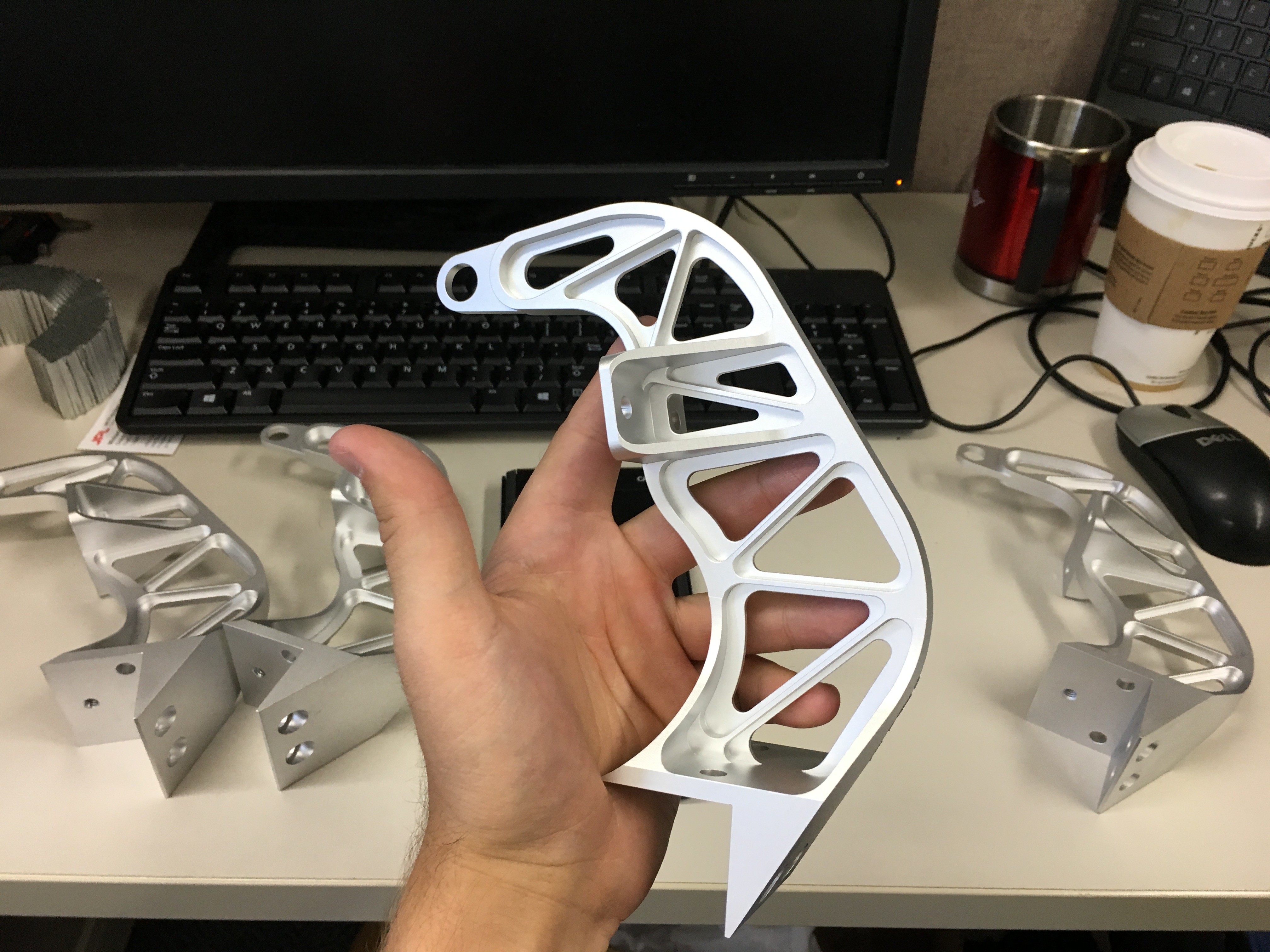
Finished compliant anchor ready for integration.
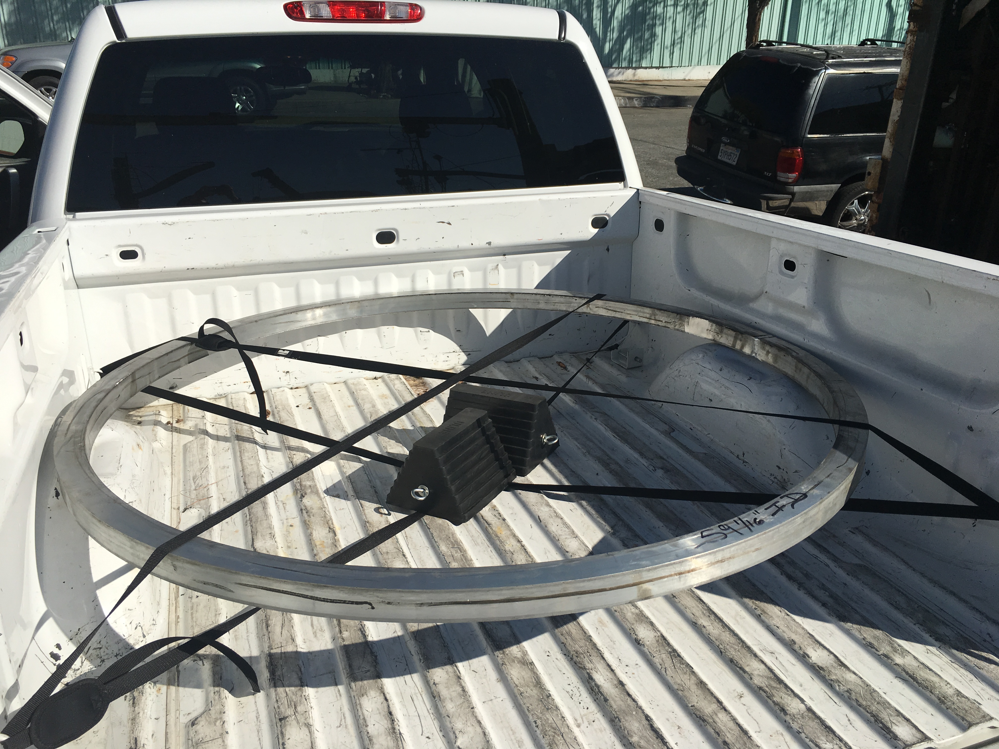
Picking up strong back from tube bender.
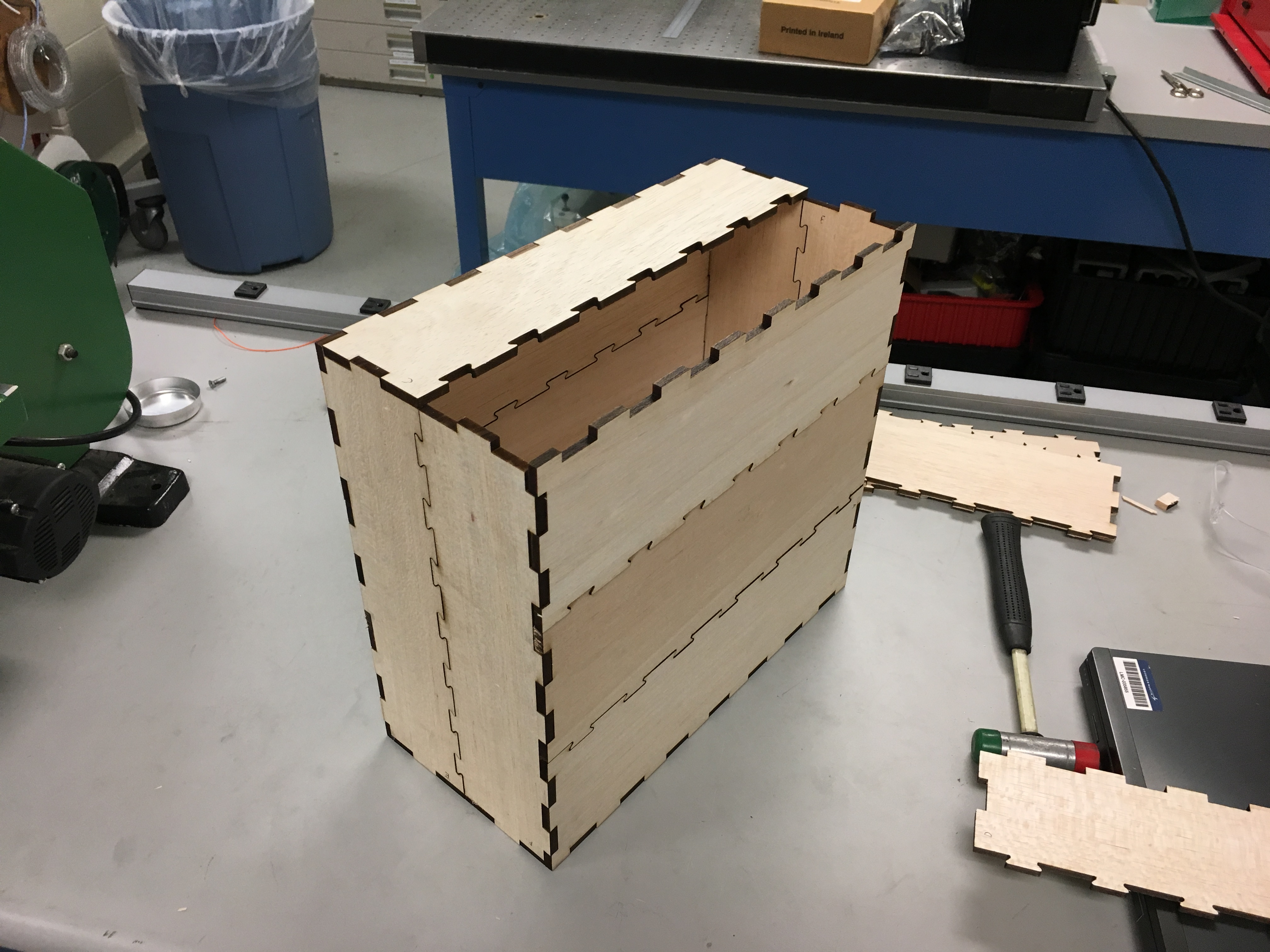
I designed the battery boxes to be laser cut out of balsa.
This model was intended to be a functional test-bed, so while designing parts, I used FEA to inform my decision making and ensure the parts could withstand estimated worst case loading scenarios. Shown above to the left is the compliant anchor which was the interface between the compliant member on the stabilizer and the strong back.

“Hip Assembly” completed, these interfaced the stabilizers and compliant members with the strong back.
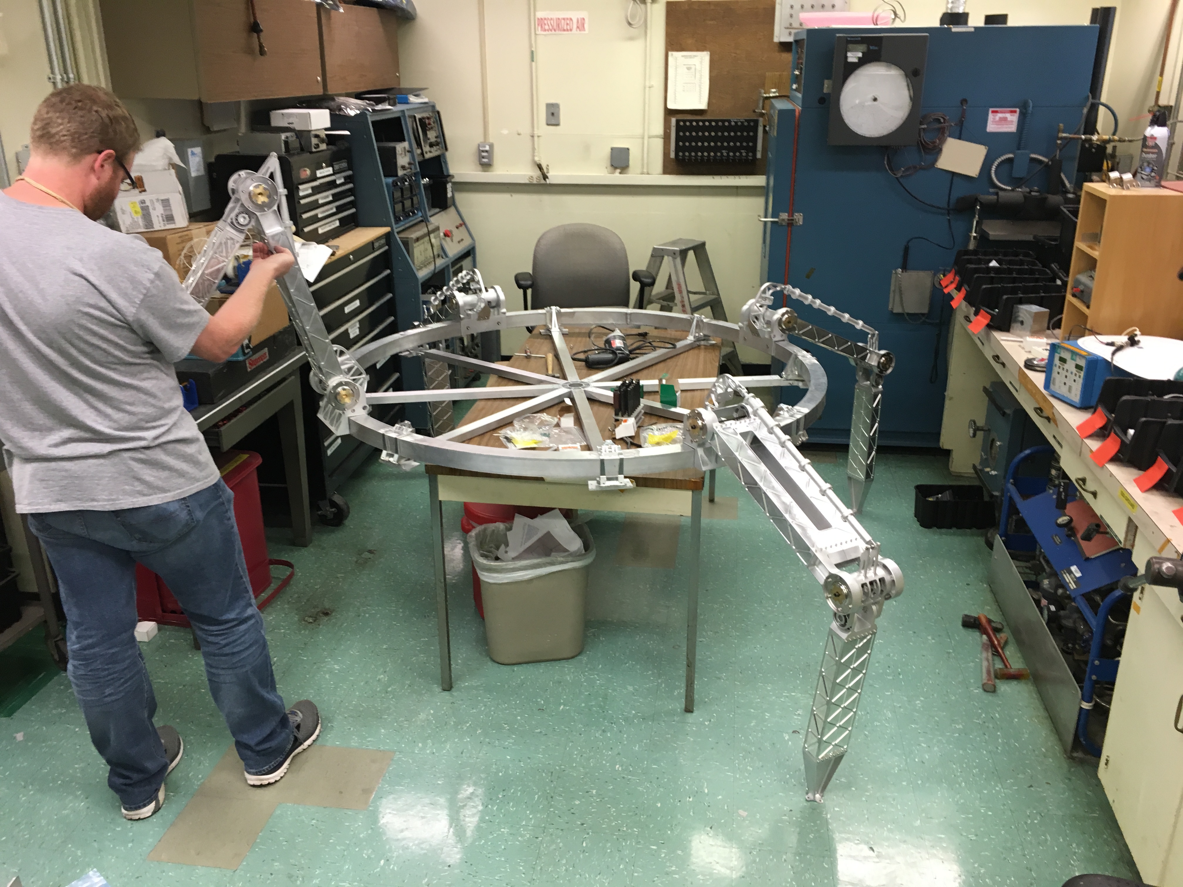
Integration of stabilizers with strong back.
I was in charge of the assembly process so I conversed with vendors, manufacturing engineers, machinists, and technicians to get the job done fully and on time.
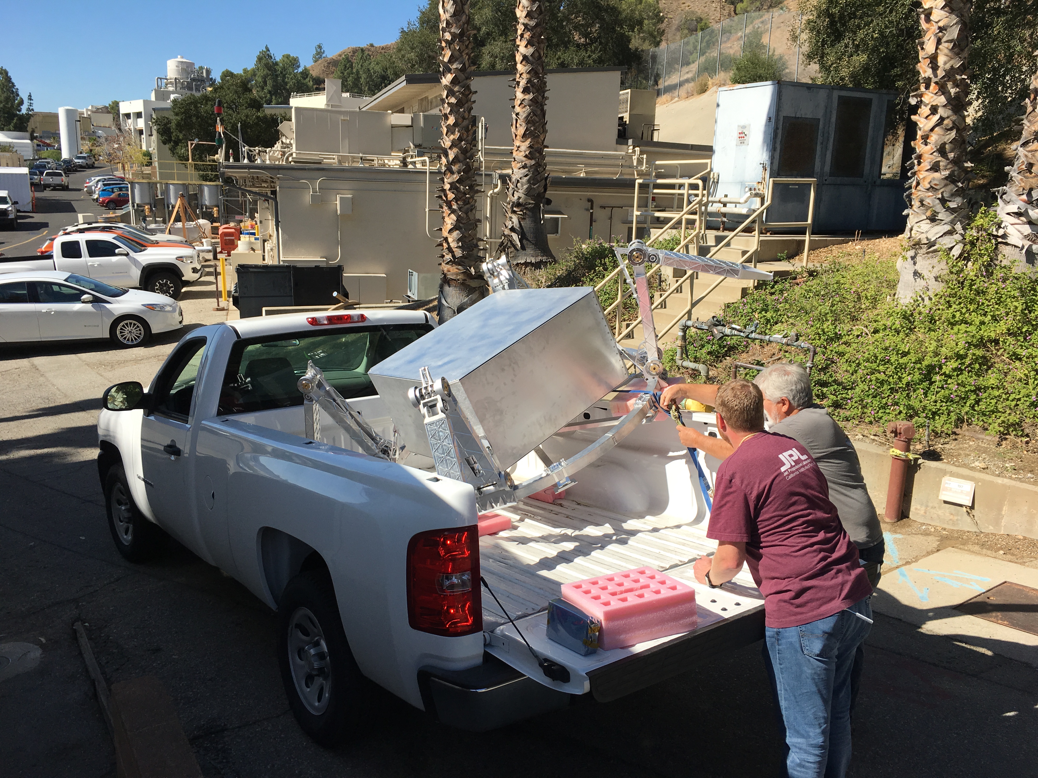
Lander almost complete, on its way down to the conference room for integration of the belly pan and feet.

Final assembly of belly pan. Honeycomb traction pods shown being adhered to belly pan.

Lander complete just before Delta MCR!
It was really rewarding seeing my project quite literally “in the spot light” during the Delta MCR. The lander model was received excitedly by everyone and often brought up during the review as physical evidence why the mission was ready to move into Phase-A.

Lander model featured in the front of the room at the Delta Mission Concept Review
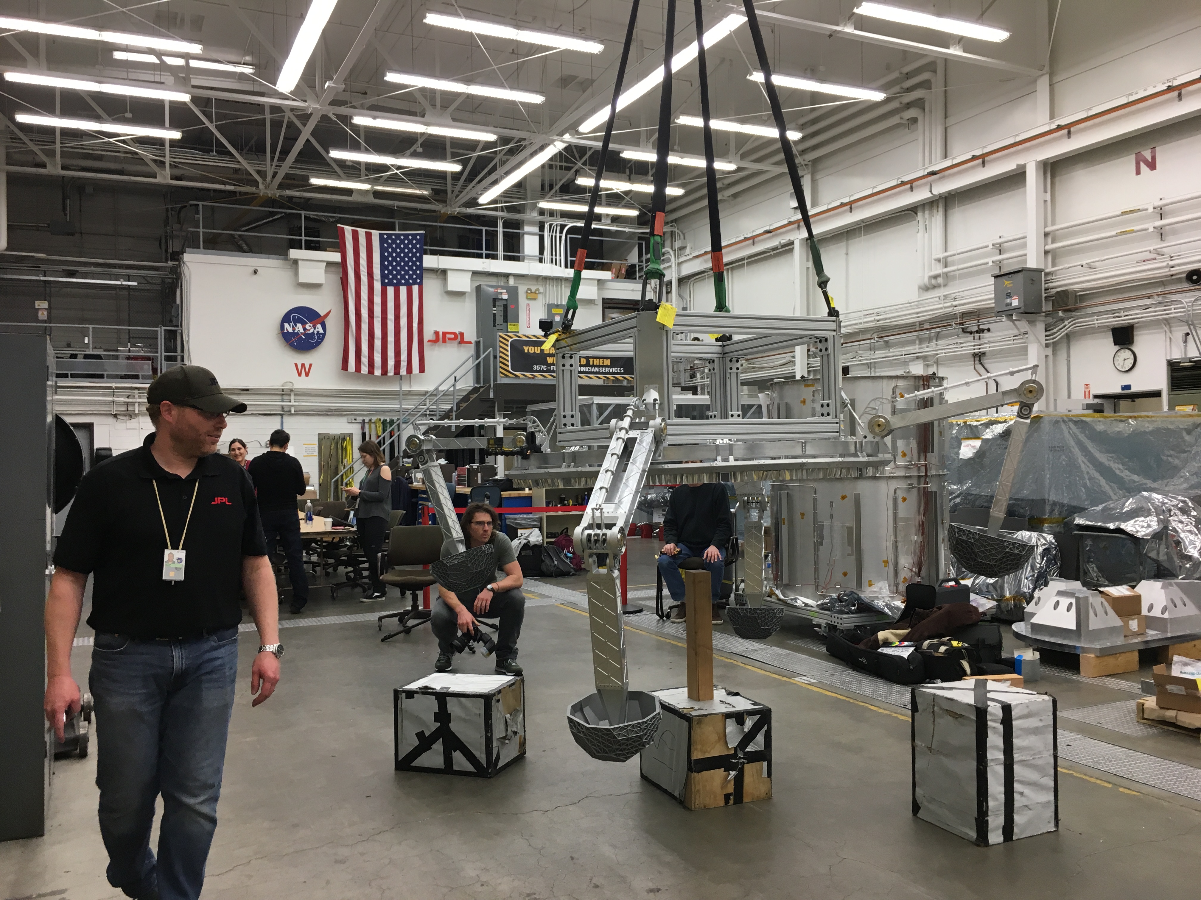
Lander hoisted on crane to physically test performance.
To conclude my Co-op, I built a frame to attach the lander to a crane and performed physical drop testing. This was to characterize its performance and see how it behaved in comparison to the ADAMS computer simulations.
