Project Description
Autonomous Flying Wing

In this project I set out to make a Flying wing that could be flown in First Person View (FPV). This meant having a camera onboard transmitting in real time over an analog 5.8Ghz signal to a monitor on the ground. I would fly the plane via the monitor rather than looking directly at the aircraft. I also used an ArduPilot Mega flight controller which could be configured to execute full autonomous flight.

The build started out with two wire cut expanded polypropylene (EPP) wing cores made by RiteWing and some fiber glass wing spars. The spars were fiberglass and not carbon fiber to reduce the chances of any radio frequency (RF) obstruction with the 433MHz, 2.4GHz, and 5.8GHz signals which were going to be used for telemetry, control, and video. There was also two winglets and some film which would be used to laminate the wing.
After inserting the spars and glueing the wing halves together, the battery location needed to be determined. The batteries were the heaviest part of the aircraft so their placement had a dramatic effect on the center of gravity (CG). The CG needed to be about 2/3 the length forward on the root wing cord. With this in mind, I placed other components on the wing roughly where they would be mounted and found where the batteries needed to be balance everything out. Once this was marked, I hotwired out the battery and electronics bays.
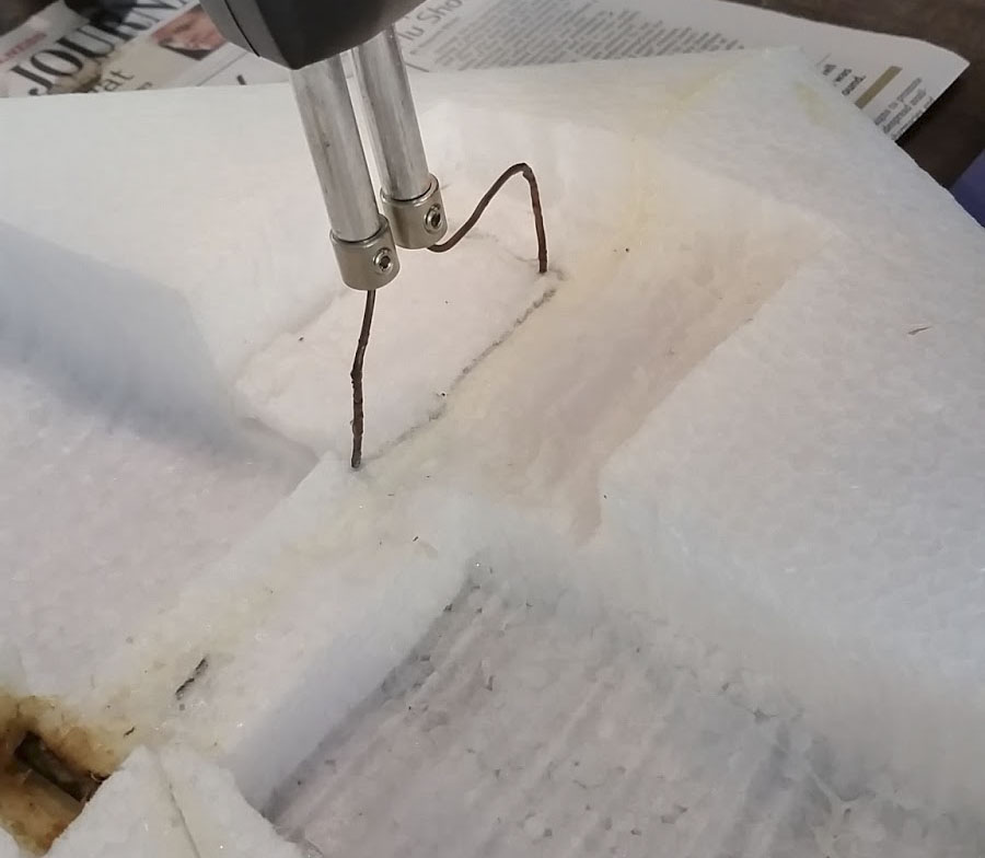

This wing used two control surfaces called elevons (electronic mix between elevators and ailerons) to control pitch and roll. One servo was placed in each wing half to control these elevons. The wing was passively stable in the yaw axis due to the large winglets. I also cut a channel down each wing half to route cables to the video TX, telemetry TX, Rc RX, and GPS modules which needed to have as much separation as possible to mitigate the chances of RF interference.
I laminated the wing using an iron. 3 mil film was used for the wing top, 5 mil for the wing bottom and a 10 mil section created a skid plate. Note, mil is a unit of thickness referring to a thousandth of an inch. This film drastically increased the overall stiffness of the wing.


The electronics were then ready to be mounted. I originally mounted the batteries as shown and the flight controller in the forward bay, but for the CG to be correct I needed to have a gopro on the nose. This was fine for the first few flights but I didnt want to have to attach the gopro every time so I moved the batteries to the forward bay and the flight controller to the left aft bay.
The elevons were then attached using bi-directional fiberglass reinforced packing tape. I read online that if the elevons are trimmed with a 2/3 inboard taper, the rolling characteristics are much more locked in during flight. You can see this in the picture with the outermost 1/3 portion of the elevons being full width and they were cut narrower toward the center.


I am a big fan of using colored packing tape instead of spray paint. Its much more crisp and easy to replace if needed. I applied it section by section and it came out looking pretty sleek!
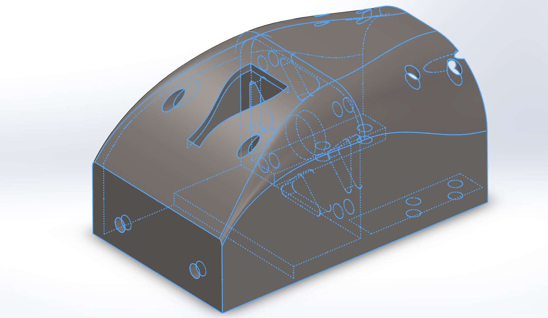
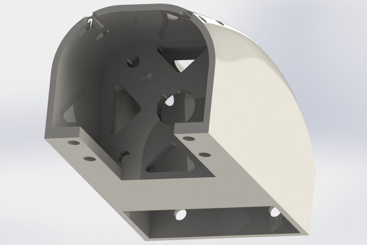
I originally made a motor mount out of 1/8″ aluminum bent into a bracket, but this positioned the motor too far back for the CG to be in the proper location. The original motor placement didn’t take into account the laminate film because I didn’t realize it would have an effect on the CG. I needed to make a new motor mount to move the motor forward. This would have been difficult to do with aluminum because of the mounting hole pattern on the fuselage so I decided to use additive manufacturing. I designed the model above in Solidworks and tossed it on my printer to be fabricated. Because I was printing this, I designed really nice looking aerodynamic geometry and even put a NACA cooling duct on it for fun.
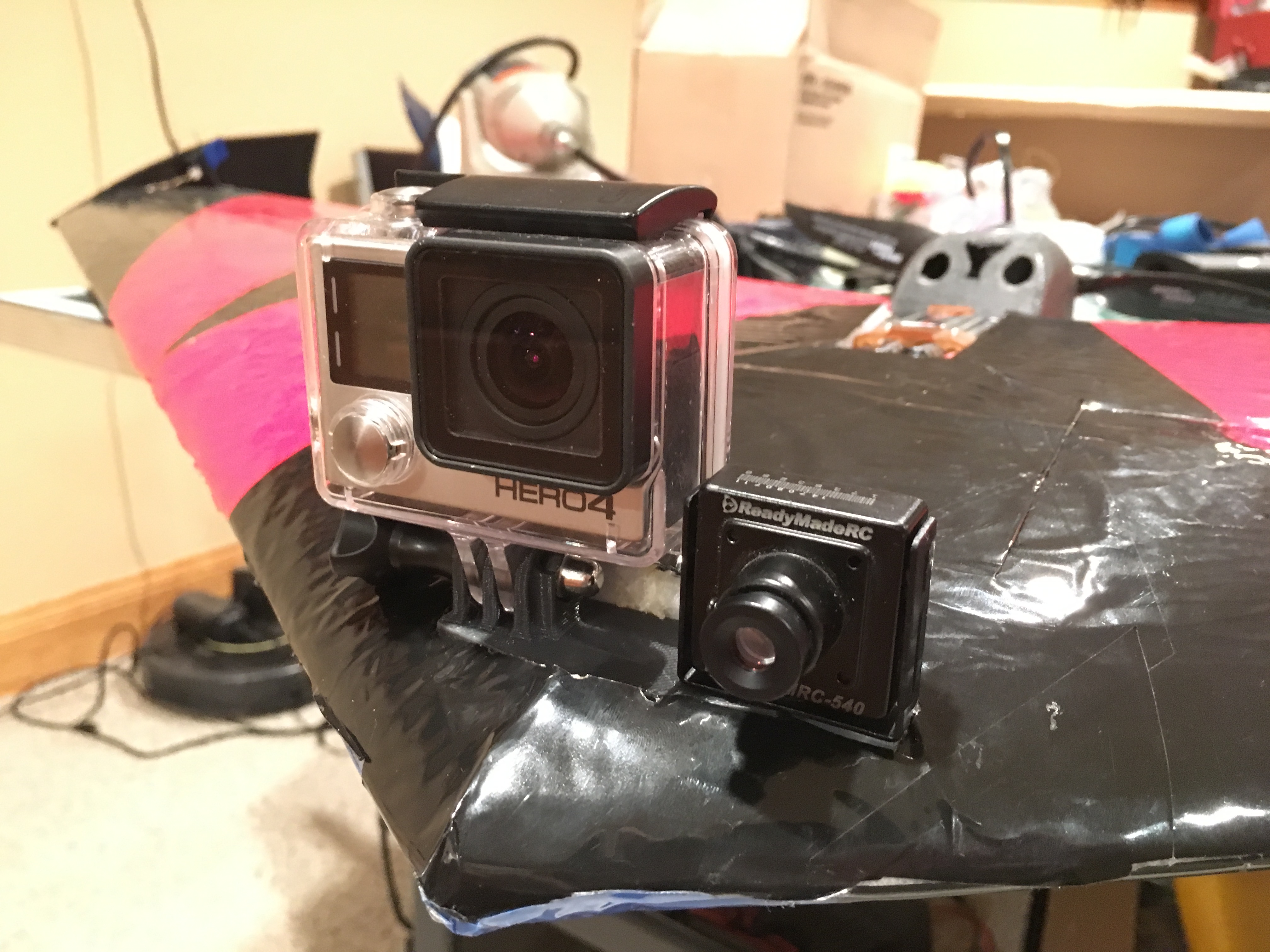

Shown above to the left I mounted a GoPro and an FPV camera to the nose using another 3D printed bracket. The GoPro was to record HD video and the FPV camera would transmit video live to the ground via a 600mW 5.8GHz analog video transmitter (yes I have my HAM license to be legal). Above to the right is the Minim on screen display (OSD). This board takes flight data from the Ardupilot and overlays it on the video so I could get vital flight data with out taking my eyes of the video. This data was also available in real time on the ground control software that ran on my laptop and communicated to the Ardupilot via a separate 433MHz signal.
It was then time to test fly. The first flight was a success although the control authority felt sloppy. I figured this was because I used too thin control rods and they were bowing slightly under compression when actuating the elevons. I replaced them with bigger ones and the next flight the controls felt locked in. Next, I wanted to start testing the autonomous flight capabilities. The first step was to fly it manually up to altitude and switch it into “auto level mode.” This mode would simply try to keep the wings level and would test the basic capabilities of the Ardupilot’s flight management unit (FMU). This worked perfectly so I then attempted to switch it into “fly by wire A mode” which would keep the roll and pitch level. As soon as I did this the plane took a steep dive and it was too low to recover so it went straight into the ground. Surprisingly the wing was undamaged and I only had to print a new camera bracket. I reviewed the video of the crash and took a look at some flight data and noticed that when the wing was holding altitude it actually had to fly with a considerable angle of attack and the FMU was attempting to level the pitch which made the wing sink rather quickly. There was a parameter to adjust the level position in the Ardupilot firmware so I went ahead and entered a value that set the level position to be about 5 degrees nose up (actually some value in radians). I flew it again and switched it into FBWA and it again pitched down but I made sure I had enough altitude this time so I could recover. I adjusted the parameter and tested and kept repeating until I had actually maxed out the offset value in the firmware and it still wasn’t holding level pitch. I finally just 3D printed a shim to prop up the Arudpilot and physically adjust the offset. This worked!
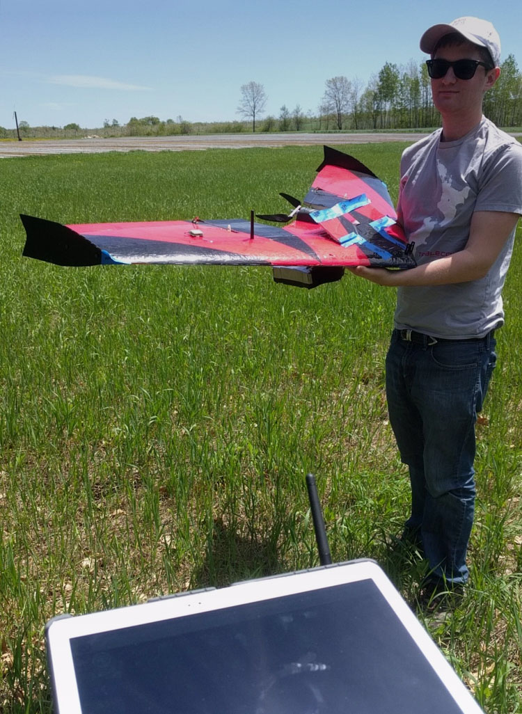

The next step was to start testing the GPS functionality. To do this I first tested the “fly by wire B mode.” This mode did the same as FBWA but also attempted to hold altitude using GPS data. This worked well and I then had one final test before I could attempt way point navigation. This was to test “loiter mode” which when activated the Ardupilot would fly circles at a predefined radius around its current GPS Location. This first test of this went really well and was a major step because this was the first time I could take my hands off the controls and the wing was flying completely autonomous. I could even look down at the ground control software and see the wing’s flight path plotted on Google Maps and it was a perfect circle despite the wind!

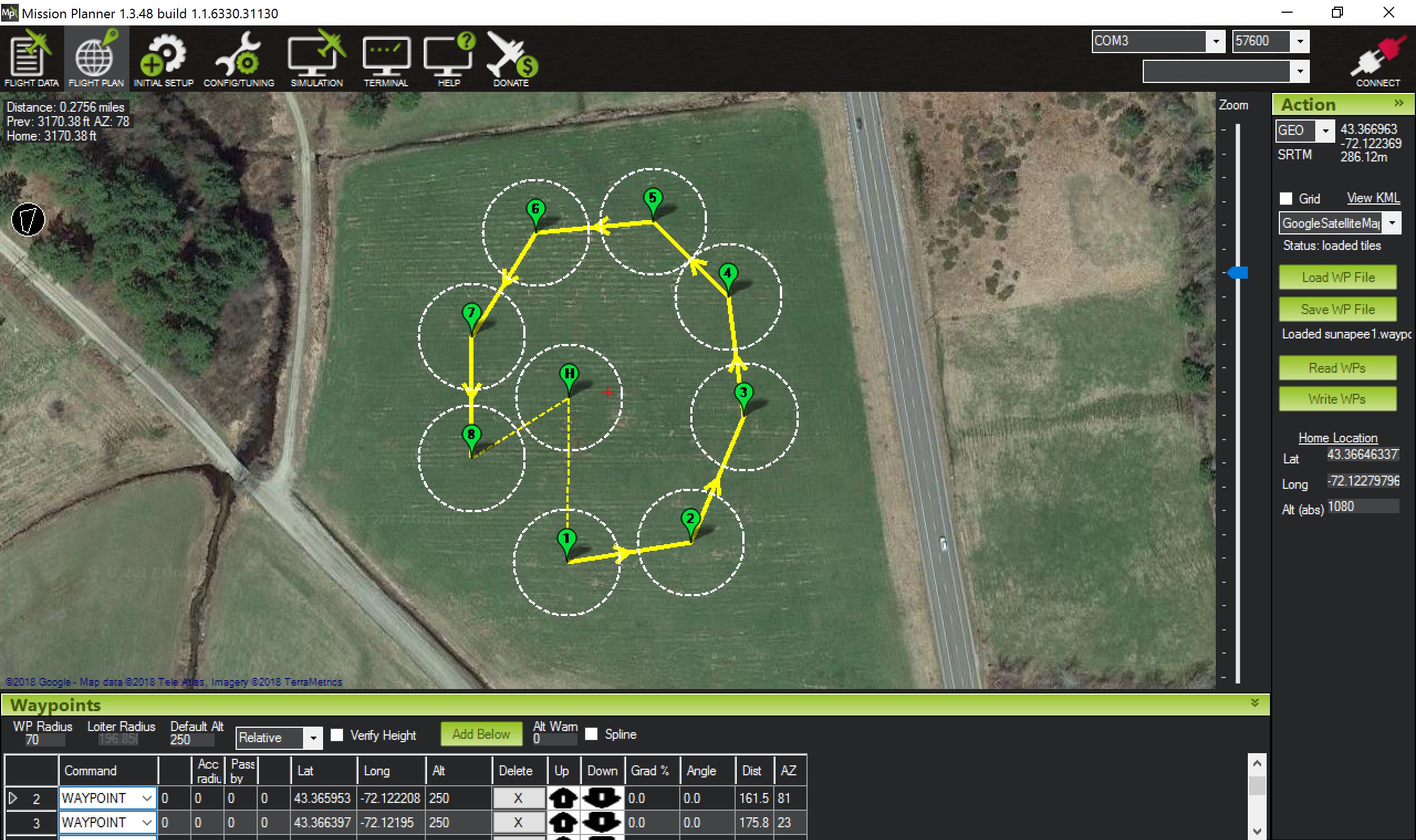
It was then time to test the full autonomous flight capabilities of the wing in “waypoint mode.” I programed waypoints around the field as shown above to the right in the ground control software and uploaded them to the Ardupilot. I could set a target altitude, radius tolerance, and speed at each waypoint as well as other conditional functions. The first test of this went well although the target altitude was set a little too low. In the future I will explore longer range missions and other functions such as return to home and auto land.
