Project Description
Tiltrotor Delivery UAV
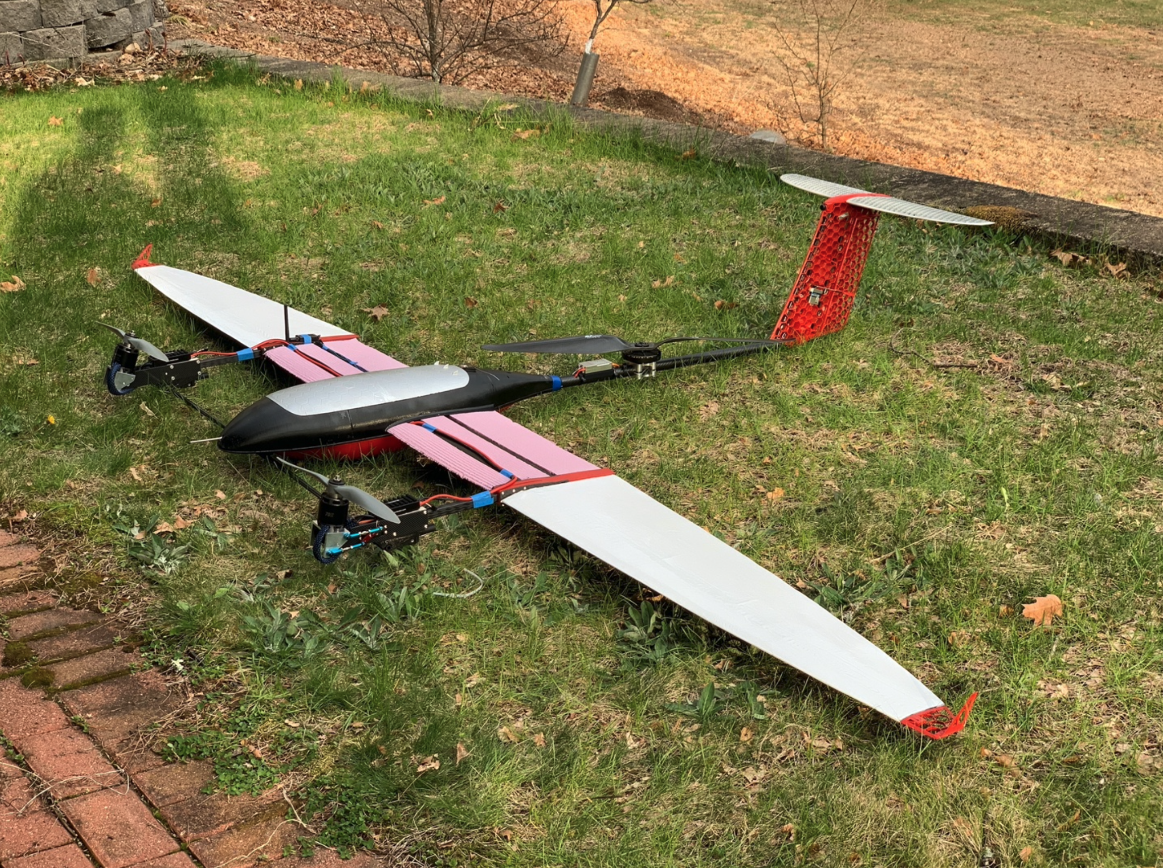
Final prototype build.
Delivering units of blood was chosen as the focus payload for this project because it is the most needed medical supply globally and has many shortfalls with its current distribution methods. Today, there are UAV systems designed for delivering units of blood and other parcels, but they all have limitations. For this project, the UAV design focused on improving the size, speed, and range of blood deliveries from existing solutions. It incorporated vertical takeoff and landing (VTOL) functionality to eliminate the need for ground support equipment for launch and recovery. This enabled return deliveries and more flexibility in where the UAV is operated from, which is useful for disaster relief. A three-rotor electric propulsion system provides thrust for sustaining vertical flight and two of the rotors gimbal forward to provide thrust in horizontal flight with a wing to provide aerodynamic lift. This configuration enables rapid takeoff and landing like a helicopter and efficient flight over long distances like an airplane, which are both critical requirements for air-based deliveries.
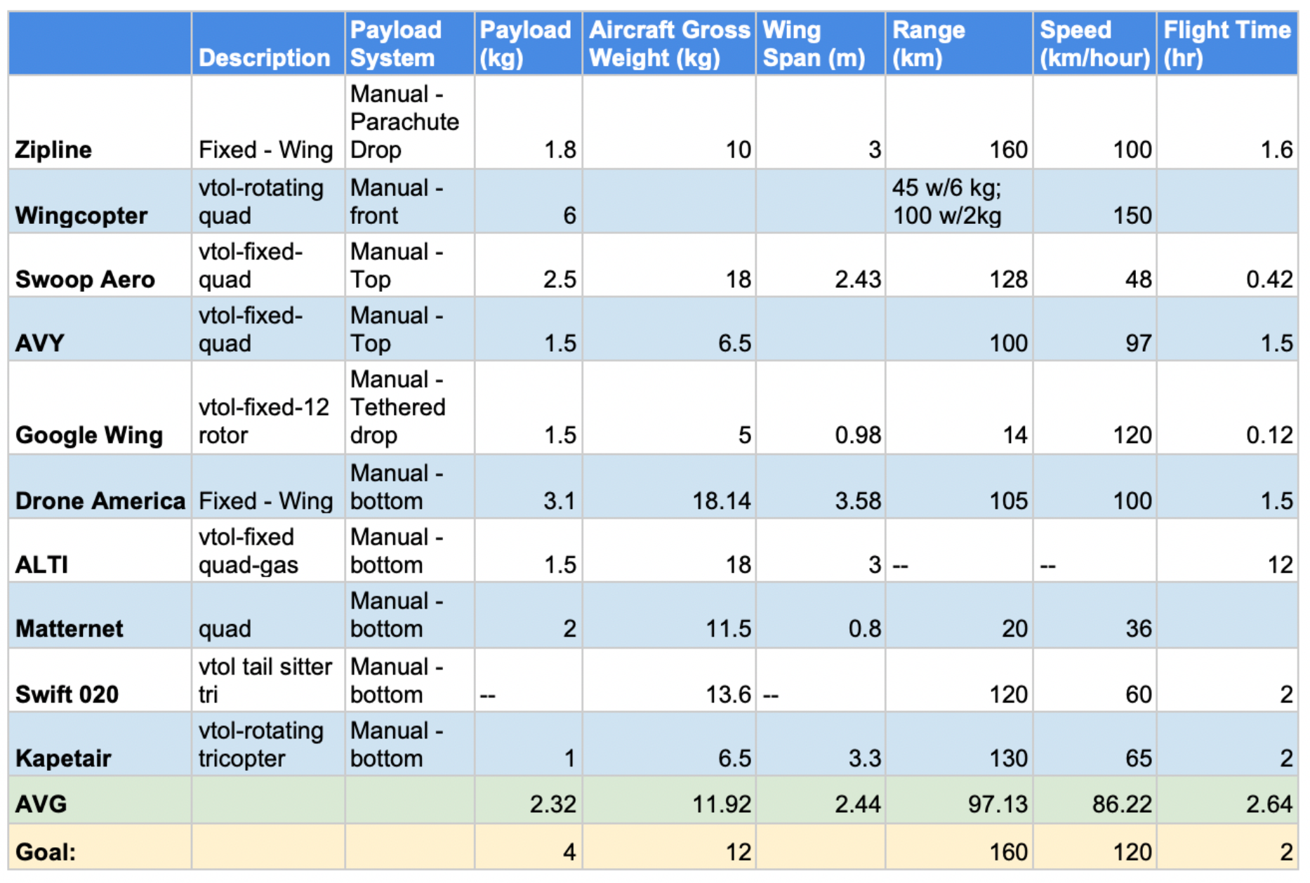
To start the design the mission specifications needed to be set. Background research was performed to collect specifications of similar aircraft which gave a starting point for the mission requirements. The goal was established at lifting a 4kg payload with a 160km range at 120km/hr. An average blood transfusion is 3 units of blood and a 4kg payload could transport at least 5 units so there was some buffer to this goal if the payload needed to be reduced later in the design. The speed and range were also slightly over the competition to allow for design creep. The range allowed the aircraft to provide service to entire islands such as Puerto Rico or connect multiple smaller islands such as the Greek Cyclades. Multiple deployment sites could be used to cover entire countries such as Rwanda.
With efficiency as most paramount, the design focuses on optimizing the three most energy dependent subsystems: payload, aerodynamics, and propulsion. These then drive the remaining subsystems of: structures, controls, and energy storage. Every subsystem is interdependent, so the final design will require several iterations, but by following this work flow, each design revision will be the most action-oriented.
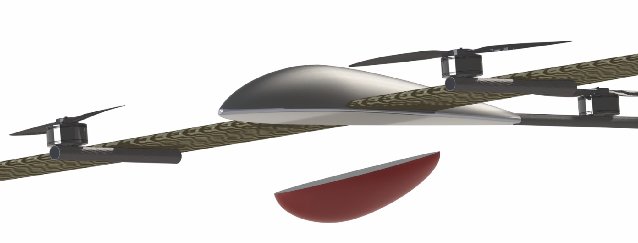
The design concept for the payload module will be an expendable package mounted external to the fuselage. This means that the fuselage can be smaller than if it had an internal bay. The smaller fuselage will result in less drag and greater efficiency on the return trip after the package has been delivered. So long as the center of gravity (CG) and center of pressure (CP) of the package line up with the CG and CP of the aircraft stability should not be largely effected when the package is dropped. The external payload also decouples its design from the rest of the aircraft so it can be revised more frequently and open to more applications later on.
Using the dimensions of 5 blood units, the overall package dimensions were set to 125mm x 125mm x 250mm.
After the payload properties were materialized, the aerodynamics of the vehicle was the first most important step to achieve the desired vehicle performance. This includes designing the wing, tail surfaces, and the fuselage.
The wing will produce all the lifting force and a majority of the drag during forward flight, so this needs to be carefully designed to be as efficient as possible. Wing efficiency is defined by the lift to drag ratio it produces at a given flight setting. This project will focus on developing a wing design that achieves peak efficiency at the target cruise speed and altitude while also balancing factors such as manufacturability and stability.
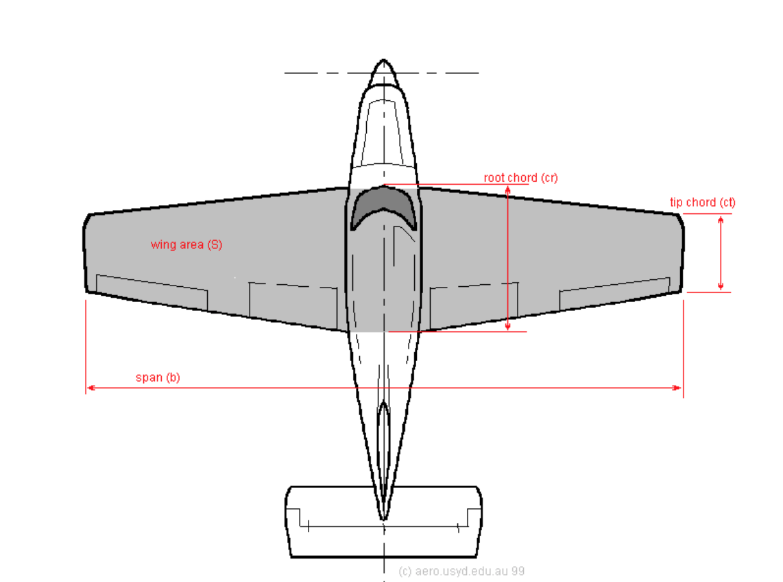
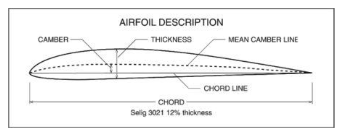
To create the wing two important elements are being designed: the planform which is the top-down shape and the airfoil which is the profile shape. The planform is characterized by the front-to-back length of the wing called the chord and the tip-to-tip length called the span. The chord at the lateral center of the wing is called the root chord and at the lateral ends it is called the tip chord. Airfoils are characterized by percent thickness which is the ratio of its maximum height to chord length. Also, camber is used to describe the curvature of the airfoil. This is measured by drawing a straight line from the leading edge to the trailing edge of the airfoil then drawing a curve connecting the same two points that maintains equal spacing between the top and bottom surface of the airfoil. The ratio of the maximum distance between these lines to the chord length is the percent camber. In general planforms with long spans and short chords, known as a high aspect ratio, produce less drag. Airfoils with less thickness and less camber also minimize drag. The wing design is intended to be as efficient as possible, so these general traits will be taken into account.
Varying the chord length along the span of the wing is called taper which is used to shape the lift profile and make the wing more structurally efficient. The lift profile is a plot of the lift force produced along the wing as viewed from the front. The theoretical best lift profile to minimize drag is one that decreases elliptically along the span. The lift produced at each point along the span is proportional to the local chord length, therefore an elliptical taper will result in an elliptical lift profile. Also, if the taper follows the same shape as the lift profile, the lifting force will be evenly distributed over the entire planform thus making the wing structure the most optimized. For these two reasons, an elliptical taper produces the theoretically the most efficient planform which is why this was selected for the design. Most full-scale airplanes do not feature an elliptical planform because it is difficult to manufacture at a large scale. For the size of this vehicle, this is not an issue, especially because computer aided manufacturing and high-performance materials will be used.
The sum of the lifting forces on an airfoil acts at a single point called the aerodynamic center. This is always about 25% of the chord closest to the leading edge. This means if the wing is reinforced with a main spar, it would be best placed at 25% of the cord along the entire span. The only problem is with a symmetrical elliptical planform the 25% chord line is not straight. To get around this, an elliptical planform is often shaped from two a-symmetric semi ellipses with the leading ellipse having a minor diameter 25% of the chord. This creates a straight 25% chord line along the major diameters of the ellipses. See the image bellow for the designed elliptical planform.

Next, the span needed to be decided. As mentioned before, longer spans are more desirable, but at a certain point the span becomes too long to support loads and to transport on the ground. By looking at flight proven aircraft with similar operating specifications as this project, a 3m wingspan was decided as the best starting point. For example, the Boeing Scan Eagle UAV flies at 90 km/h and weighs 18kg, has a span of 3m while the Zipline aircraft flies at 100 km/h and weighs 10kg, also has a span of 3m. Both of these are highly optimized designs, so with this project aiming to fly at 120km/h and weigh 14kg, a 3m span is a very reasonable starting point
Now, the root chord length was investigated. This final planform dimension drives the overall area of the wing which determines the wing loading. This is the weight per unit area the wing carries. A higher wing loading means the aircraft will have a faster stall speed and thus have less forgiving handling characteristics, but too low a wing loading means extra drag. There is no easy optimum balance between this so again the ScanEagle and Zipline aircraft was used as a starting point. With this, the design features a 0.245m root chord a 24kg/m2 wing loading, and 0.58m2 total area. The image below is a rendering of the initial design.

With the planform set, the required coefficient of lift was then determined which is used to select an airfoil. This was calculated using the following equation.
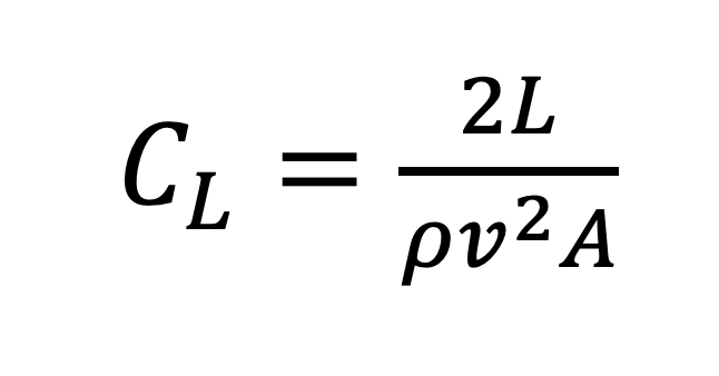
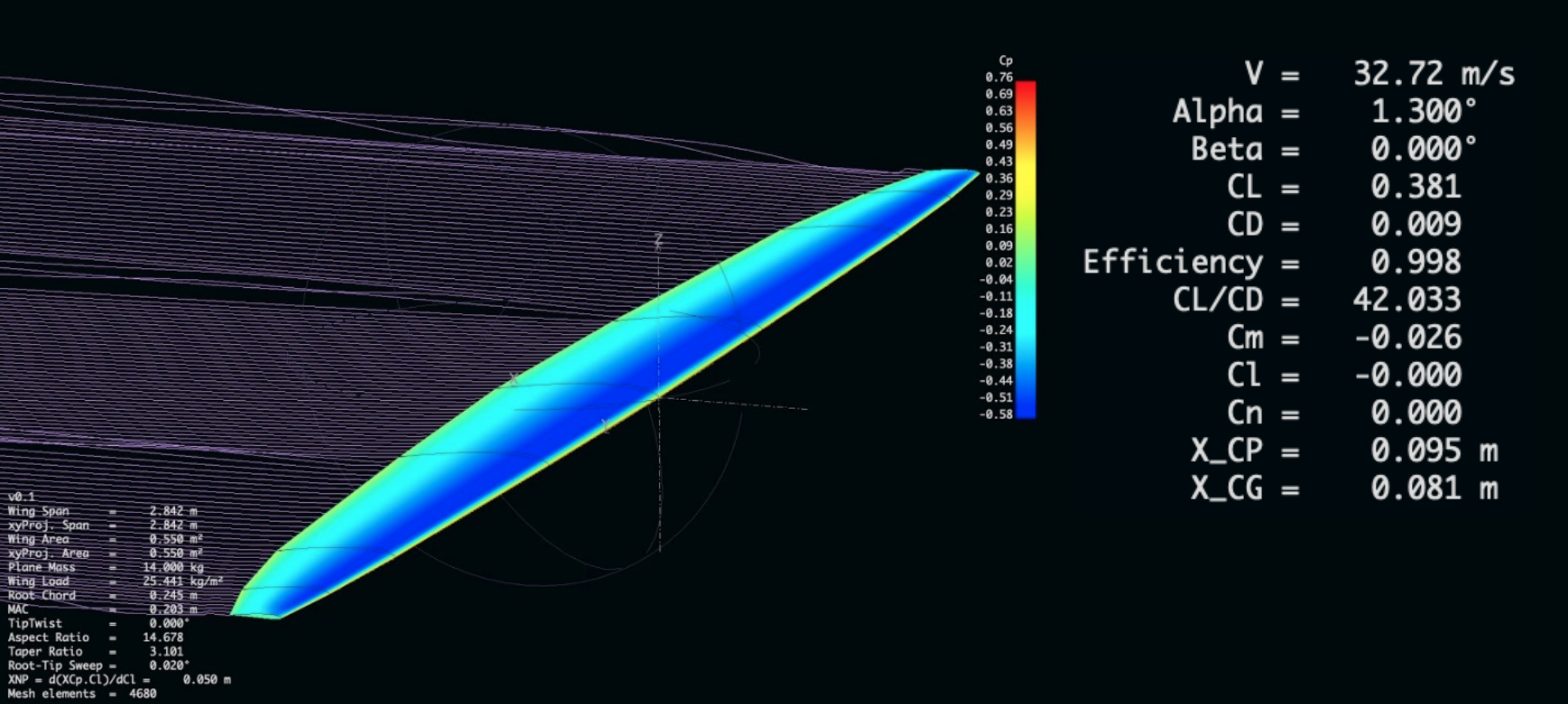
In this equation L is the lifting force, row is air density, v is velocity, and A is the wing area. This resulted in a desired CL of 0.38. The best airfoil for this vehicle is then one that creates the lowest drag at this coefficient of lift. To find this airfoil, an online airfoil database called Airfoil Tools was used to filter through 1,636 different airfoil designs. The database was also filtered for airfoils above an 8% thickness, because any thinner would not leave room for building the batteries into the wing. Also based on the mean chord length and flight velocity, the airfoils were filtered by results at a Reynolds number of 200,000. This search returned the AG24 airfoil as the best option. This airfoil was then modeled into the planform design and a simulation was run on it using a wing analysis software called XFLR5. At the design airspeed it produced a CL of 0.381 which was precisely the design goal. Also, at in level flight it was predicted to produce a lift to drag ratio of 42. In comparison, commercial aircraft operate at a ratio of about 15, and high-performance single-seat aircraft reach ratios up to 60. This means the design is on the efficient end of the spectrum. The image below shows the XFLR5 simulation.
Next the tail needed designing. In a conventional aircraft layout, pitch and yaw is controlled with horizontal and vertical stabilizers mounted behind the wing. There are many configurations to tails but most high efficiency aircraft mount the horizontal stabilizer on top of the vertical stabilizer. This is called a T-tail and it has an efficiency advantage because the horizontal stabilizer is mounted above the turbulence created by the main wing. Due to this advantage, the design for this project features a T-tail.
The only remaining component of the airframe is the fuselage. Like the other components, this will be designed to produce the least amount of drag as possible. It will function only as housing all the necessary electronics to control the aircraft, so it will be made as small as possible. Its exact size will be determined once all the hardware components are selected and laid out. This fuselage will be much smaller than most delivery UAVs because it does not house the payload.
