Project Description
Delta VTOL
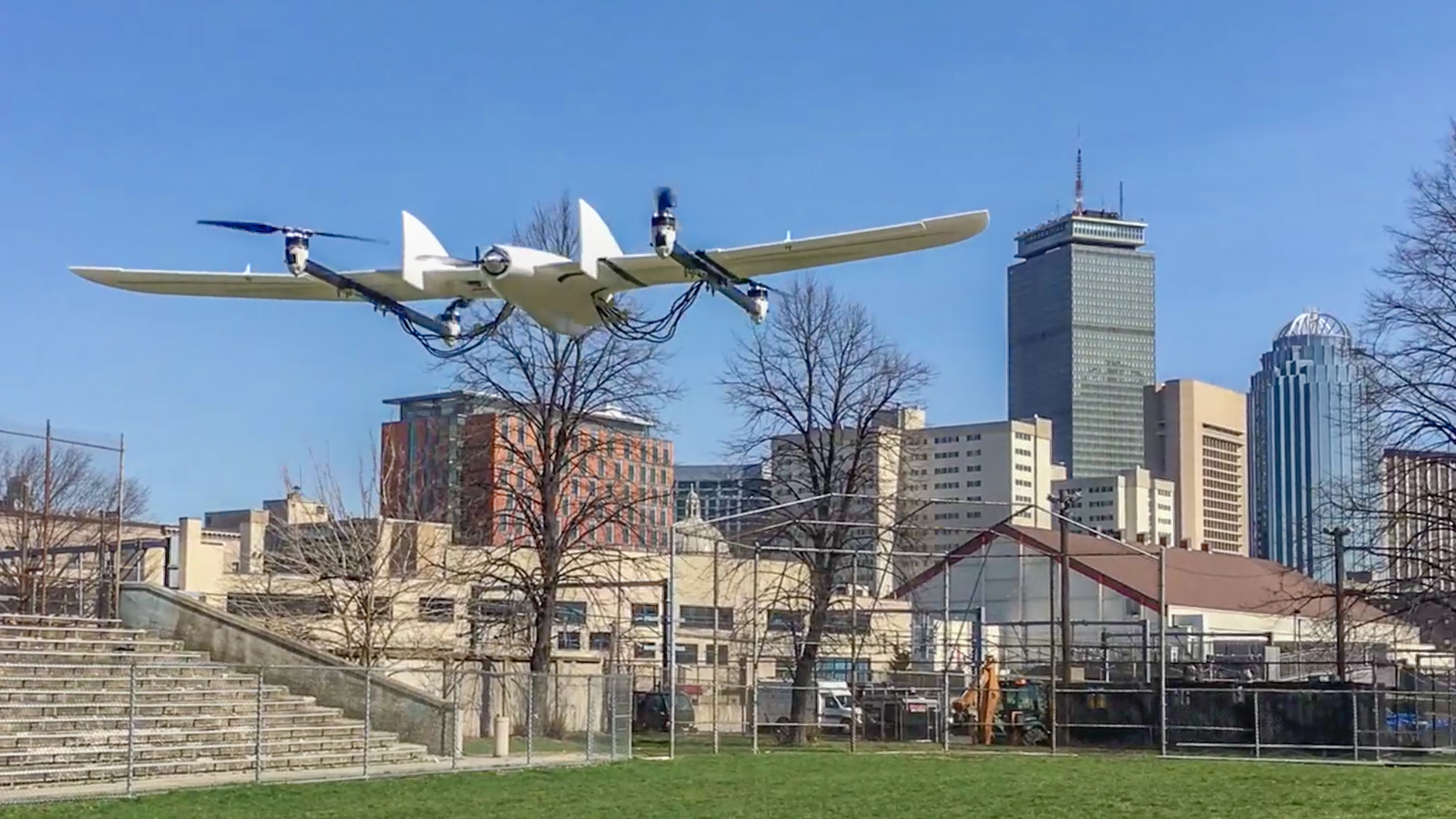
Fixed wing aircraft can cover large distances and have long flight times, but require large areas to take off and land or need launching equipment. Multirotors, on the other hand, can takeoff in a confined space but lack the range of a fixed wing aircraft. Vertical take-off and landing aircraft (VTOL) are a hybrid between the two, so if designed well they can be efficient in forward flight while being able to take off and land in a confined space. With this in mind, I wanted to see how well I could solve the challenge with a remote controlled aircraft. In the Spring of 2017 I founded an AeroNU project called Delta VTOL. The team consisted of myself and five other members with little to no experience with aviation, electronics, or hands-on problem solving. Not only was I tasked with the obvious engineering challenges, but I was also forced to grow as an educator of the subject matter and a project manager of people who had almost no autonomy.

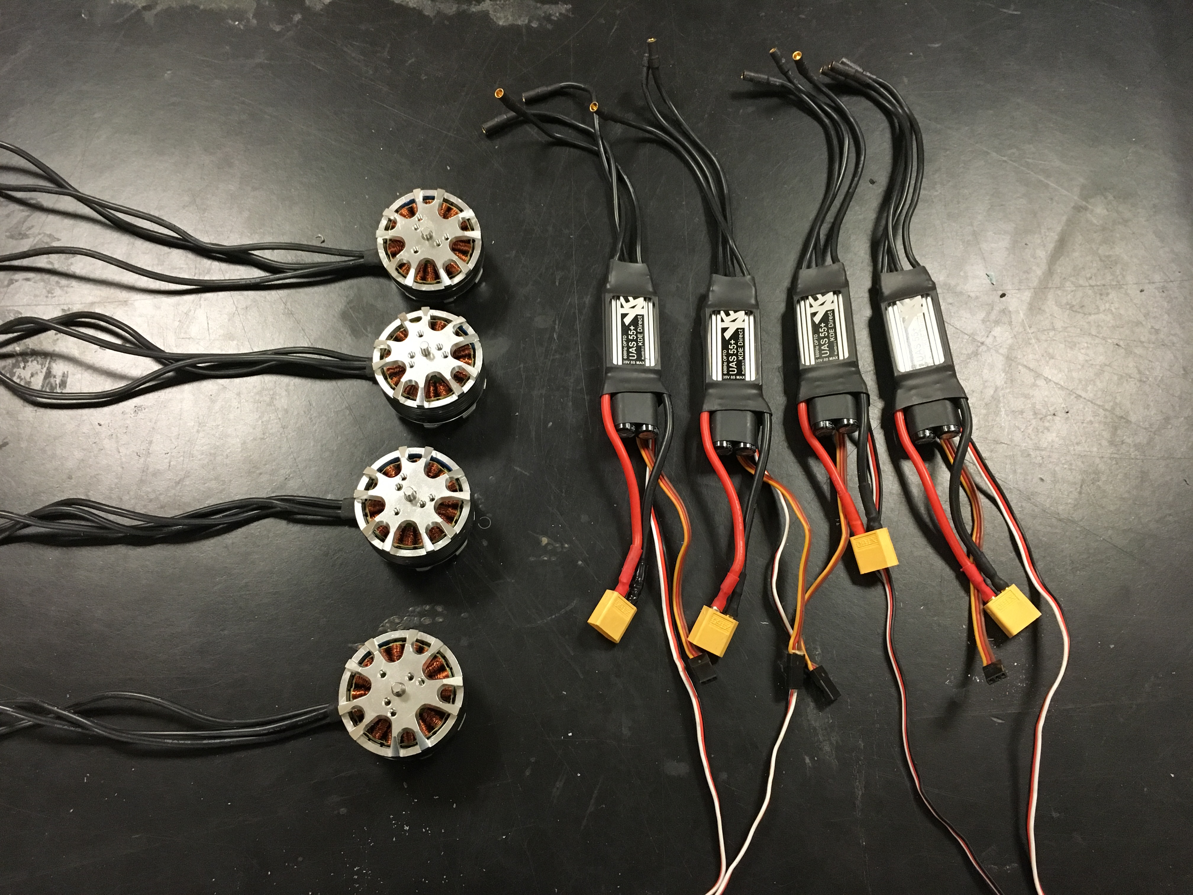
The preliminary design was to use a fixed quadrotor and fixed forward flight motor instead of articulating the quad motors for VTOL transitions. I decided this because it was the simplest VTOL configuration despite being not as efficient. I used the Pixhawk flight controller and RVJet airframe. Parts started arriving by the beginning of February. The Motors, props and ESC’s were all repurposed from a previous project. Nice KDE equipment!
Building the airframe went smoothly. Props to the folks at Range Video for really high quality EPO foam molded parts.
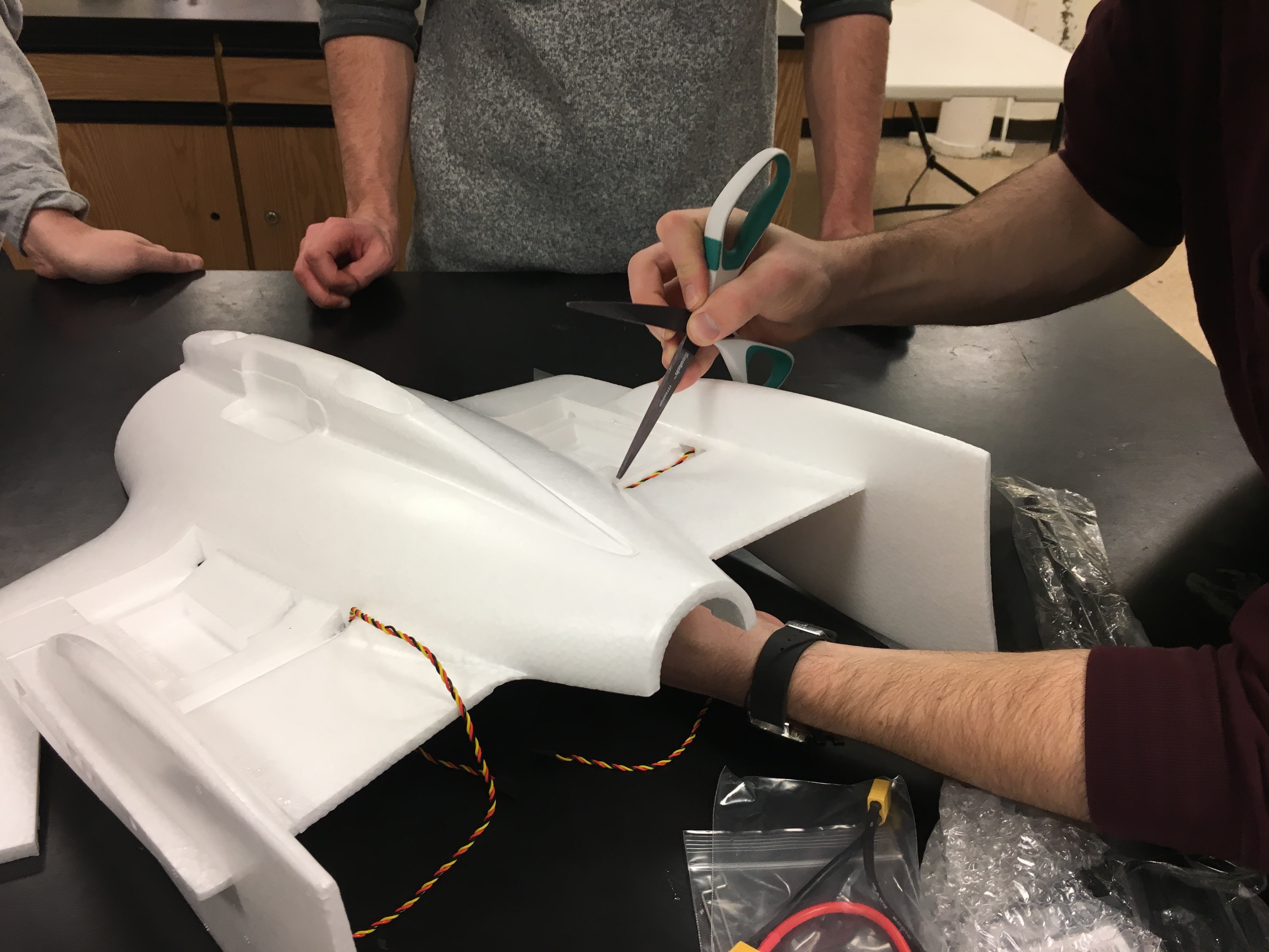
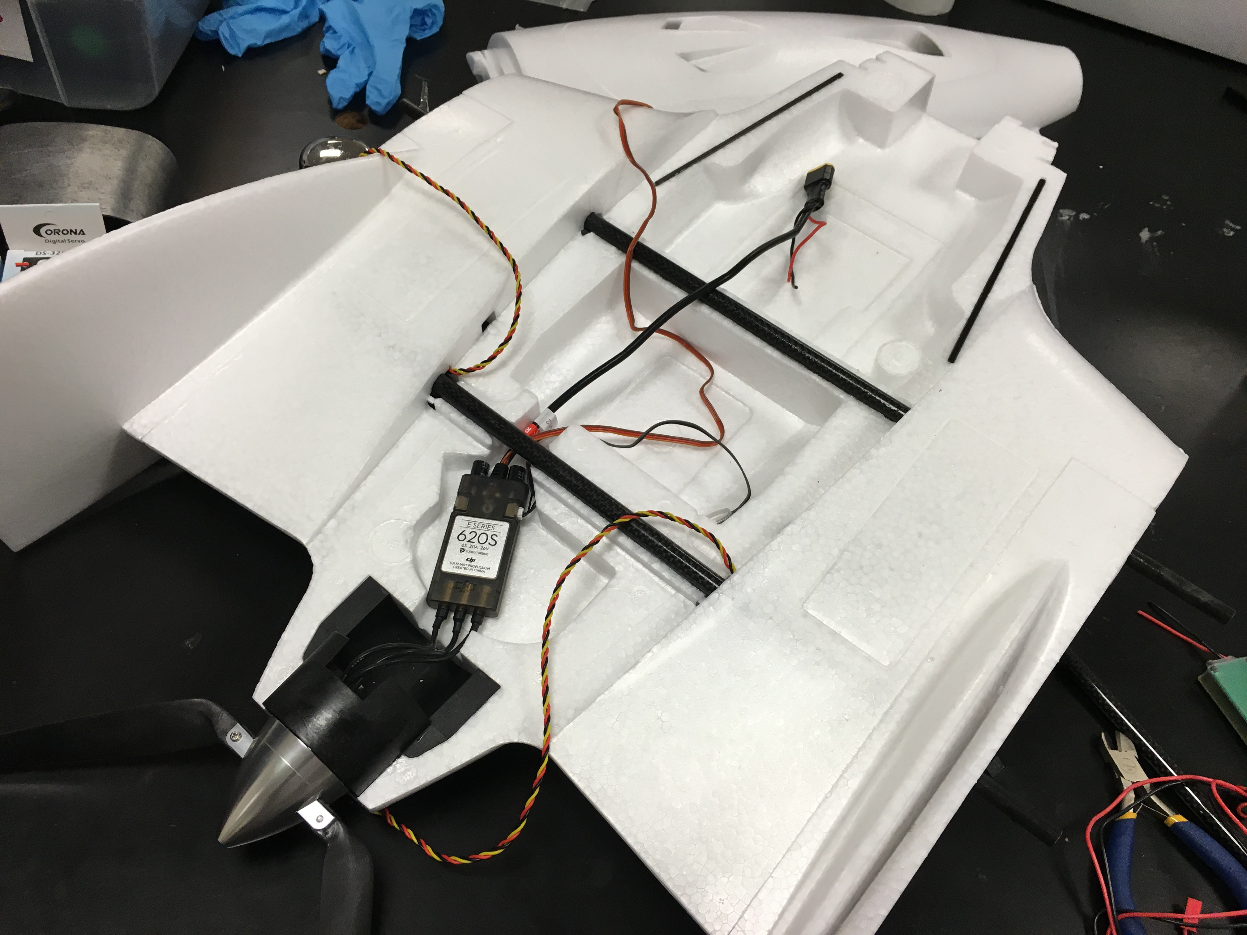
The fuselage cavity had plenty of room for the added electronics we’ll be using for the VTOL.
The two main carbon spars that run through the fuselage and out the wing sections were CA’ed into place. Each section is joined with the carbon pegs that slip in the ID of the spar.
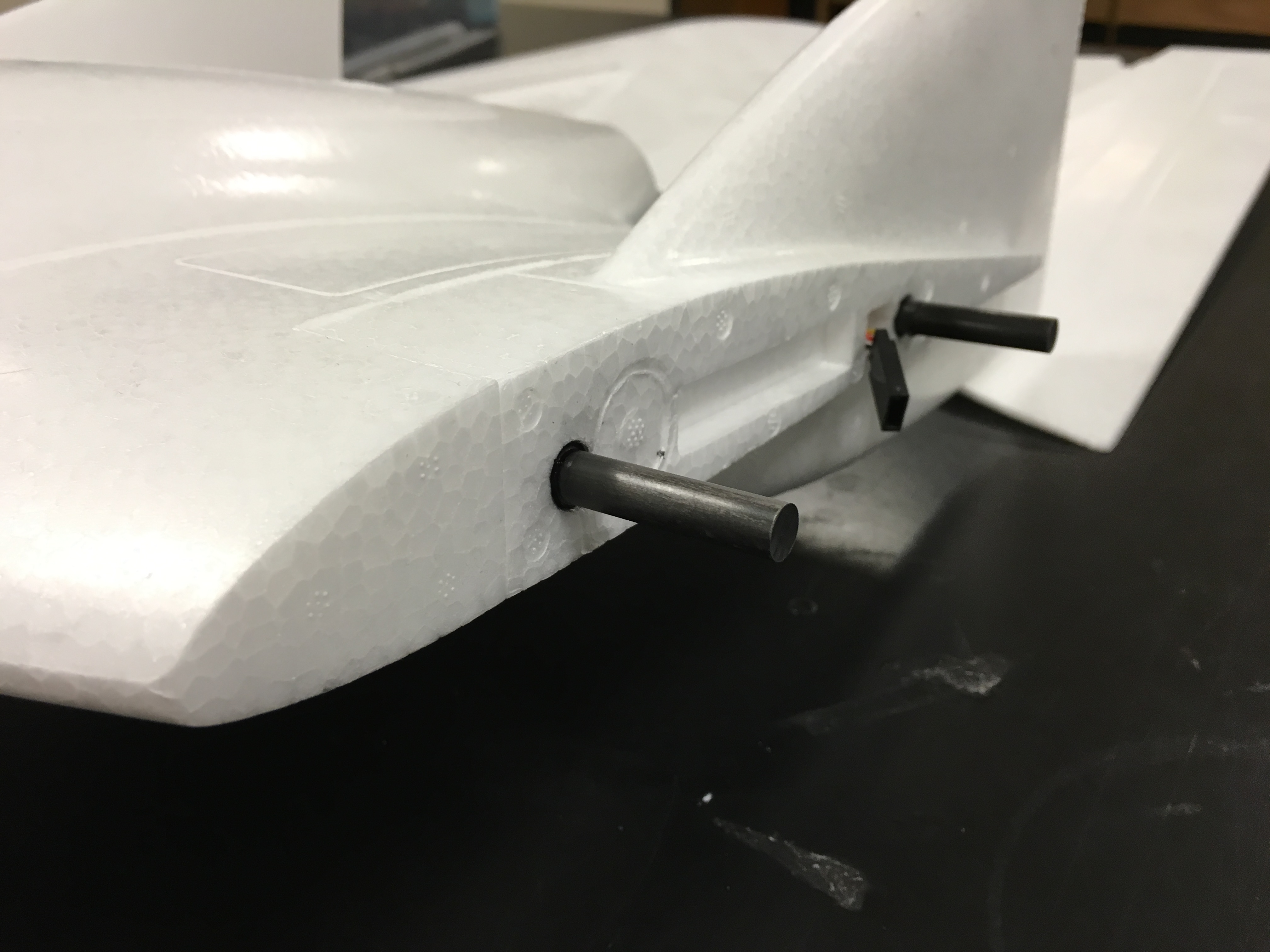
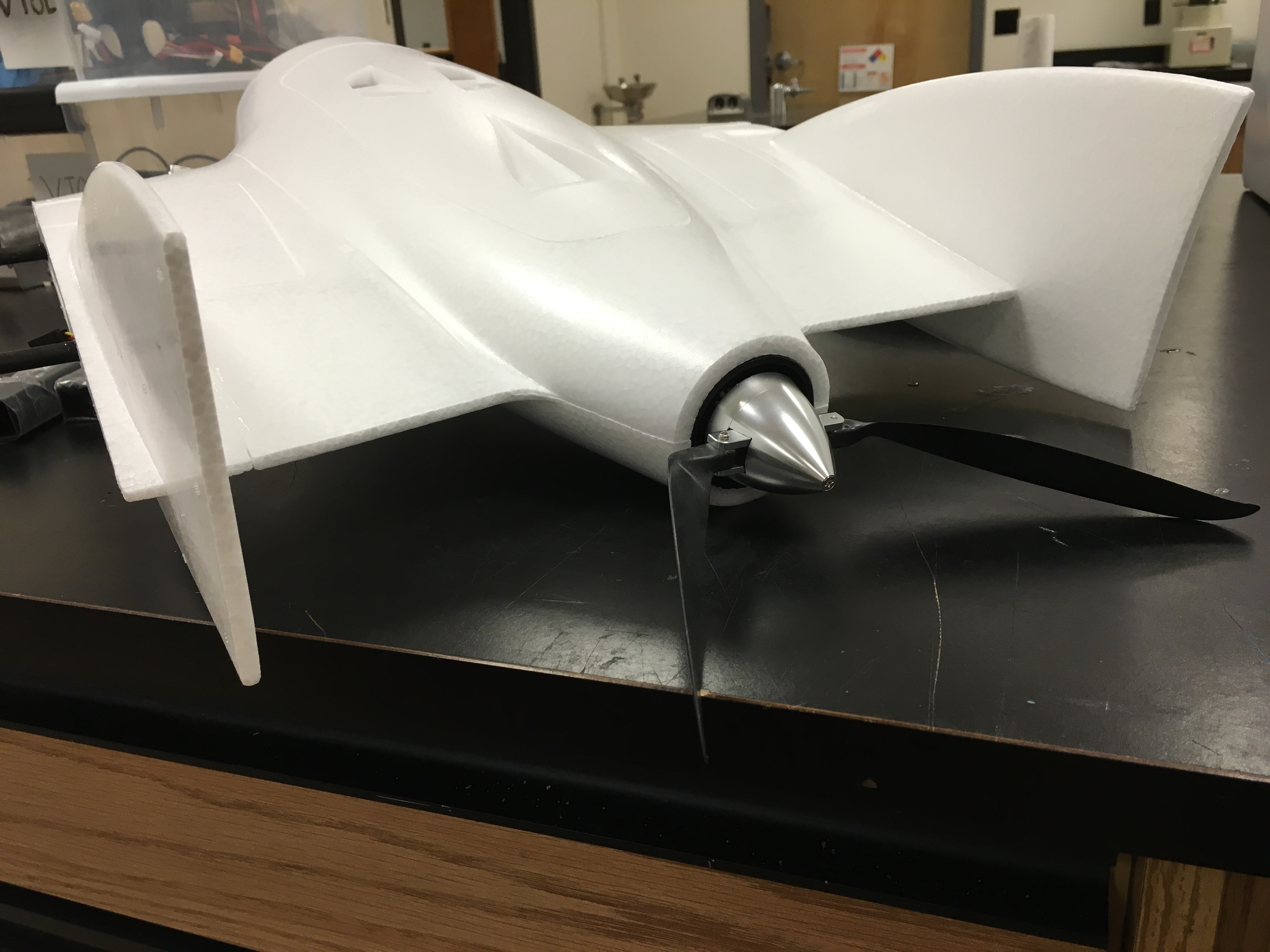
The fuselage top was CA’ed into place and there was a nice magnetic latching mechanism for easy access to the electronics. A folding prop was used so that it could be out of the way of the ground when coming in for a landing.
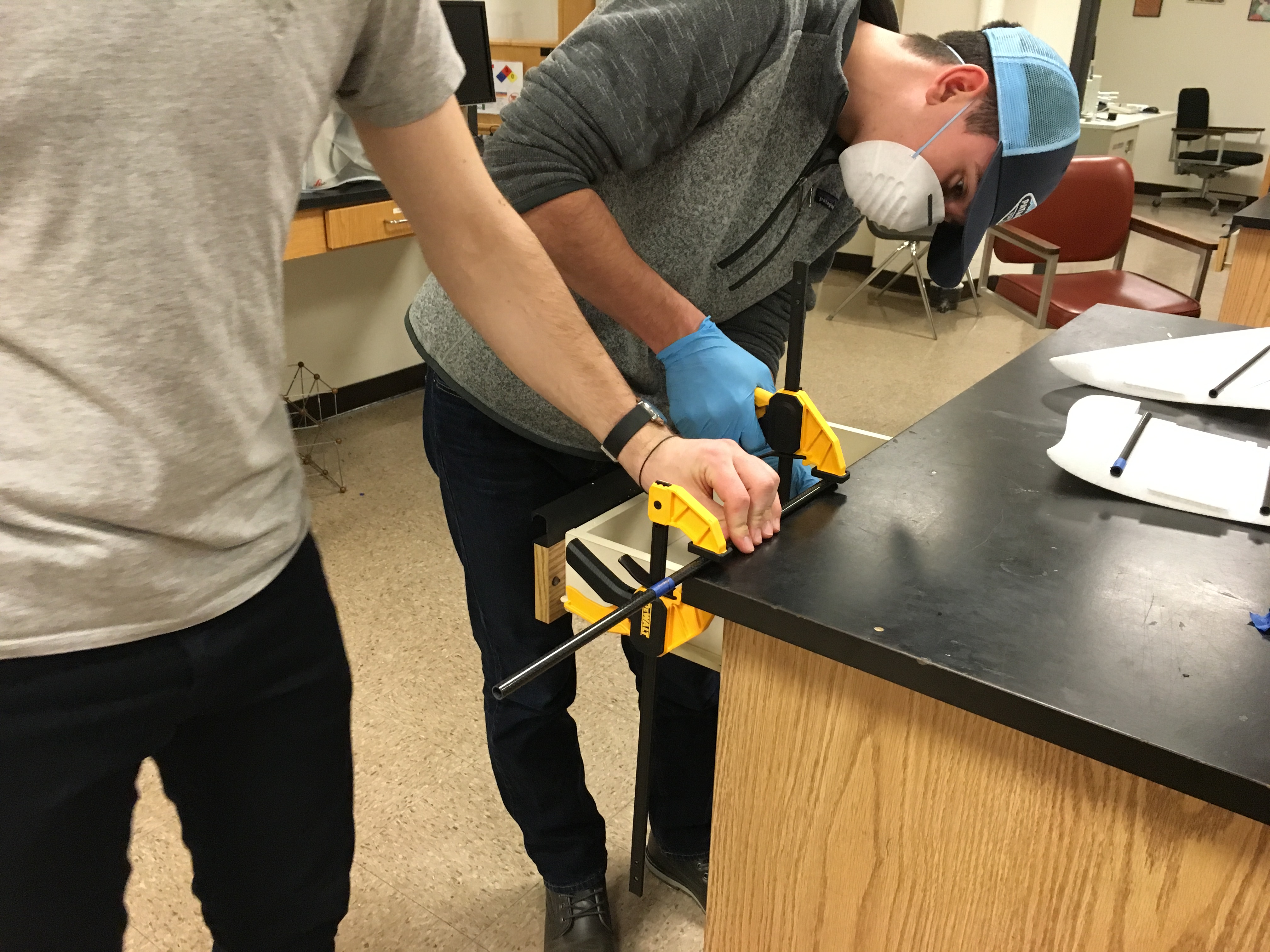
The carbon spars for the wing sections had to be cut down to the proper length. Safety first when cutting carbon fiber everyone!
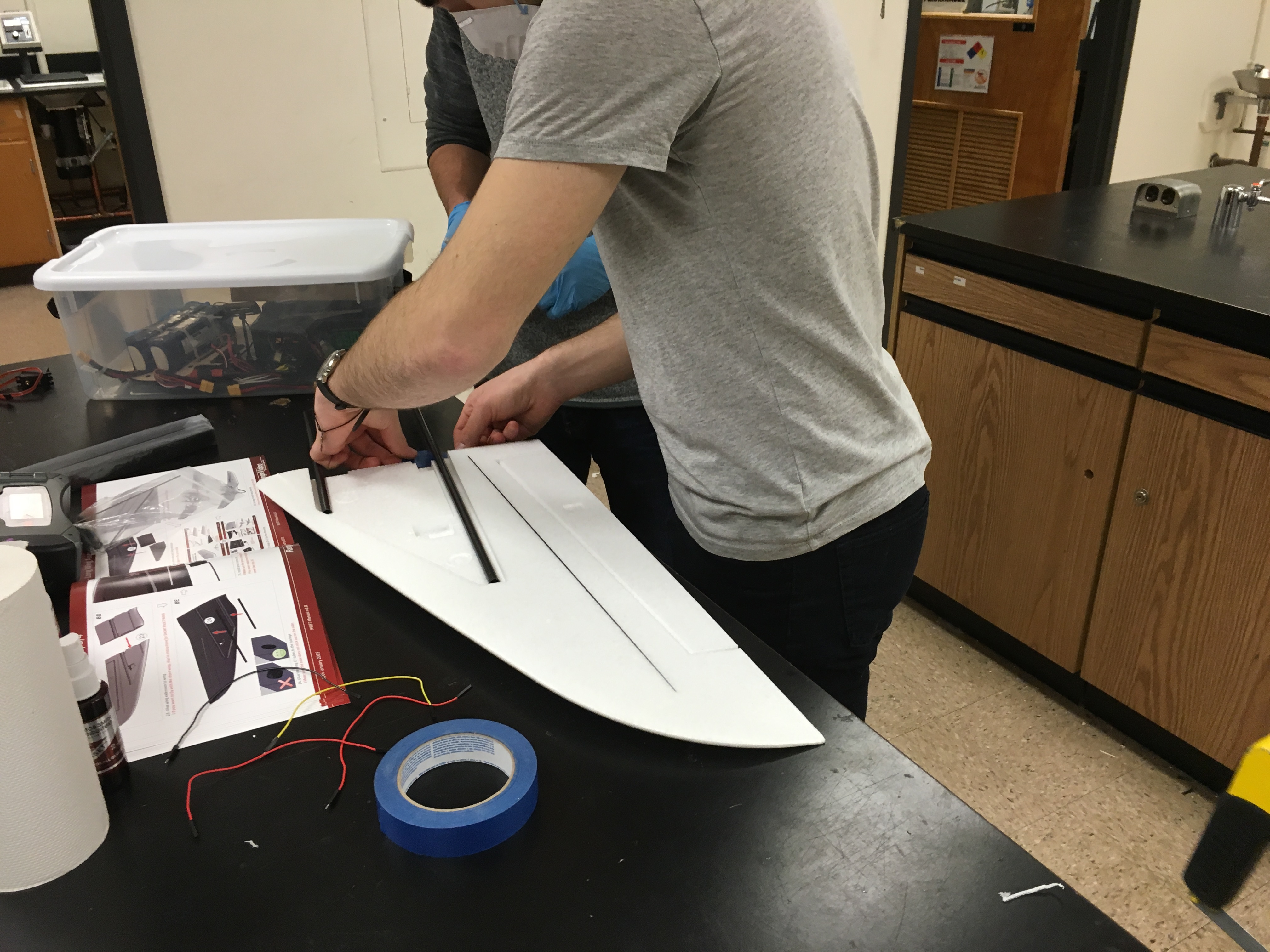
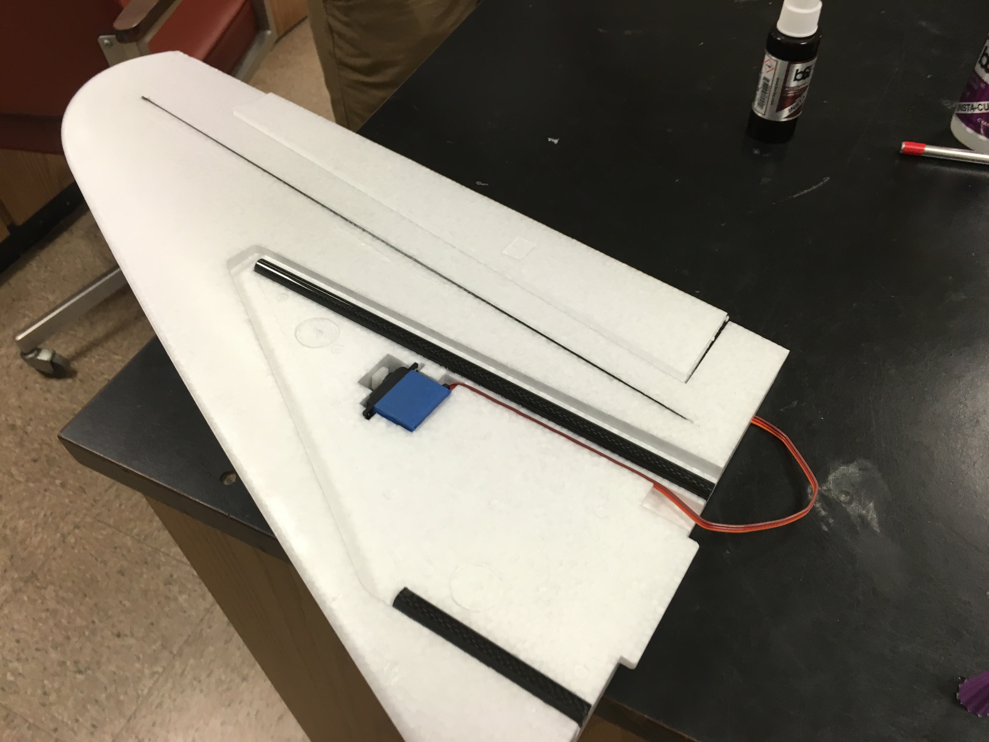
Electrical tape was wrapped around the servos before the glue was applied in case they needed to be replaced, the tape could be easily removed.
Gluing everything down and installing the elevon servos in the outer wing sections.
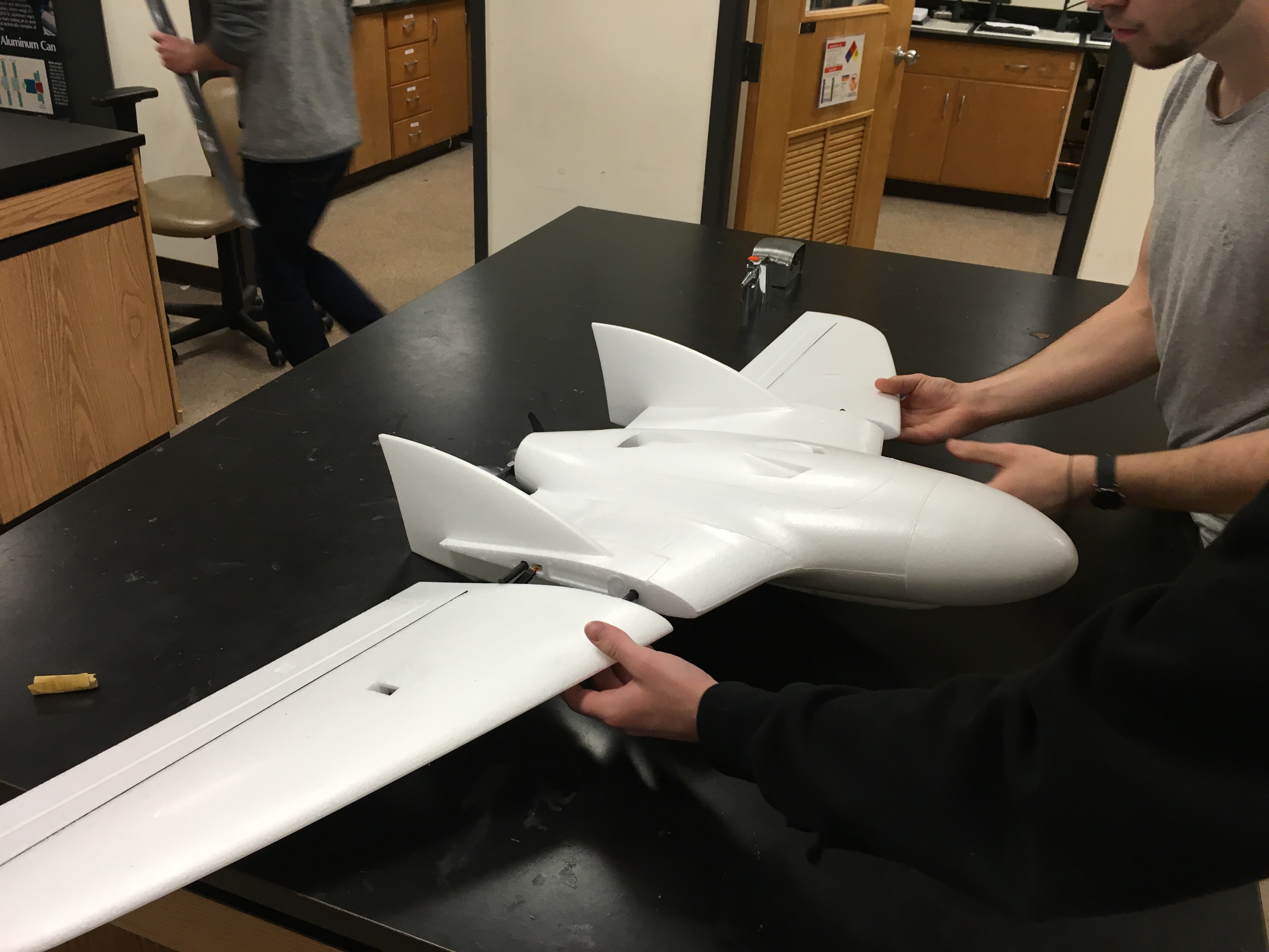
After a little sanding of the carbon tube joiners, the wing sections slid together pretty well. We will just be using tape to keep the sections from sliding apart because most of the forces on the wing are felt by the carbon rods as a bending stress not as a tensile load so the tape doesn’t need to hold much force.
Now that we were done with the fixed wing airframe it was time to start building the multirotor part. The four ESC’s were soldered to a power distribution board I picked up on amazon for cheap. This made the wiring a lot cleaner and more compact in the fuselage.
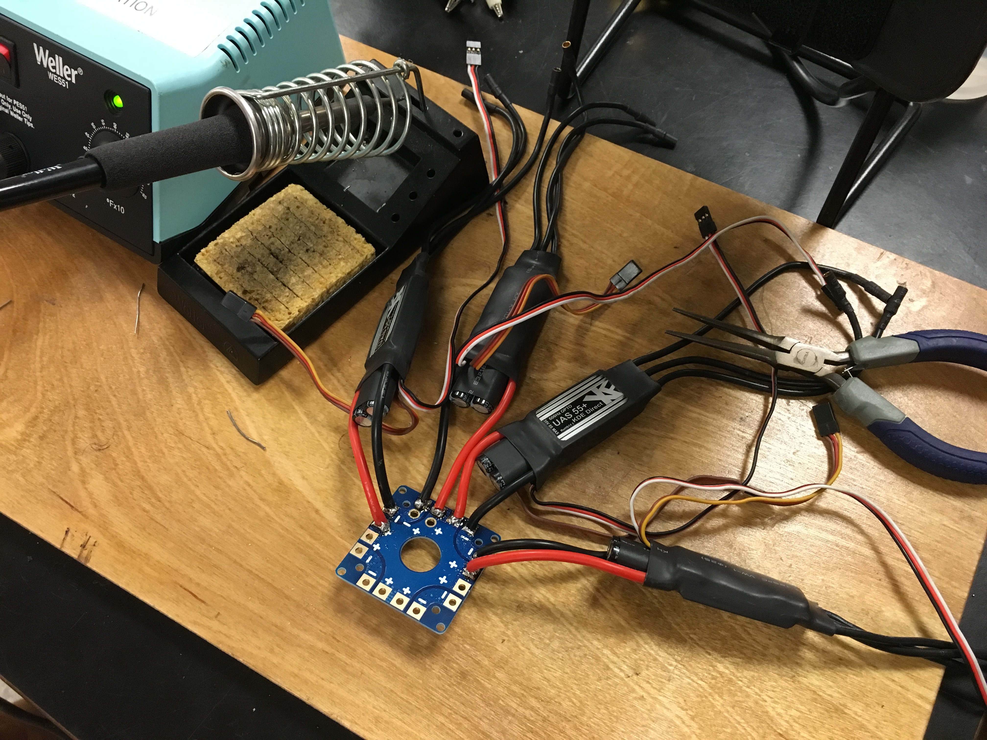
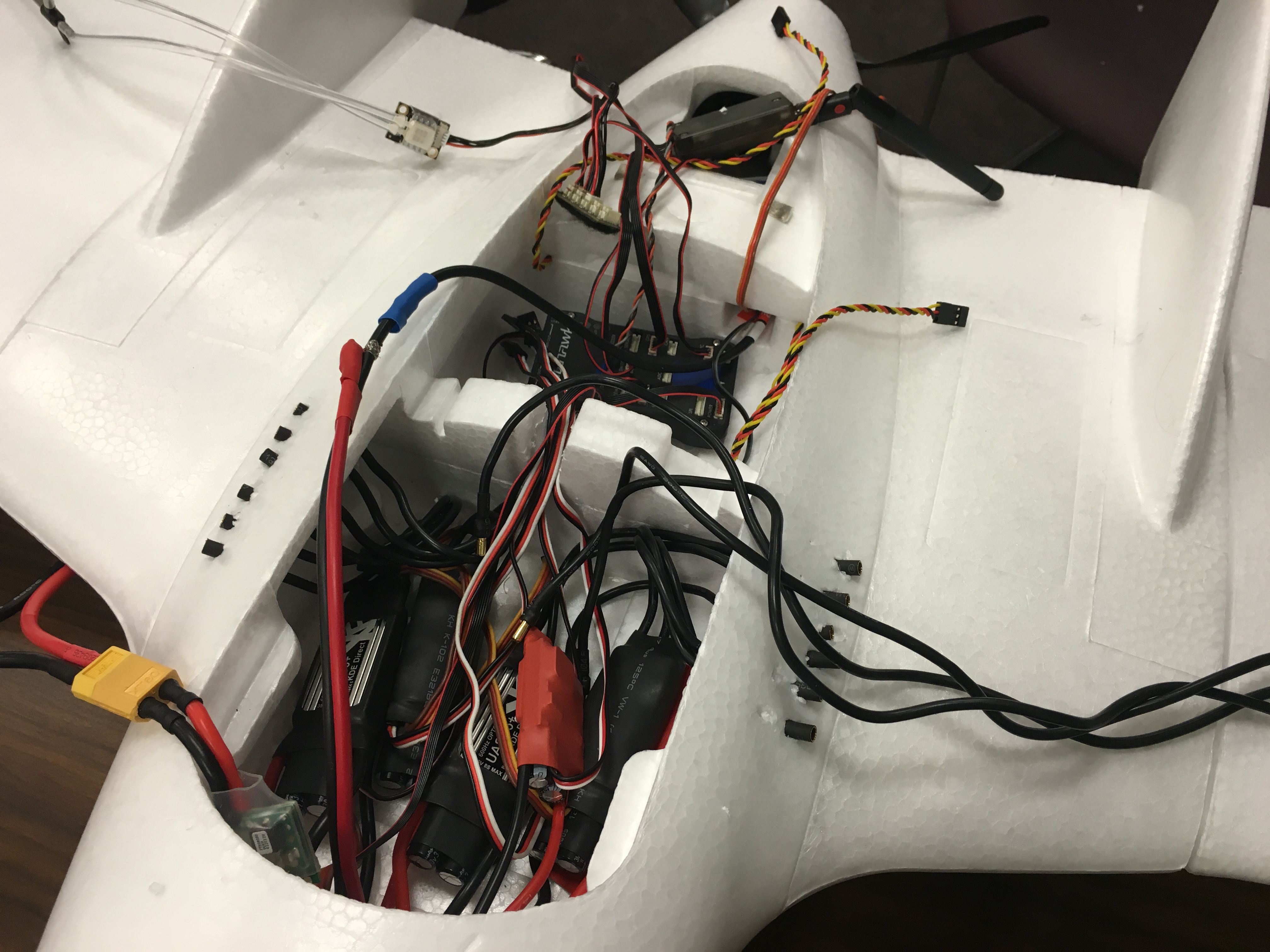
A fifth inexpensive ESC had to be used solely for its BEC (battery elimination circuit) which provided 5v to the Pixhawk output rails to power the elevon servos and the other ESC’s because they were OPTOisolated ESC’s and needed to receive power from the signal input aswell as the main power input. The Pixhawk was mounted in the aft fuselage section and a pitot tube was mounted on the right vertical stabilizer so that the Pixhawk could maintain proper airspeed over the wing while switching between VTOL modes.
Now I just had to figure out how to mount the multirotor configuration. A quick order of bolts from McMaster did the trick!
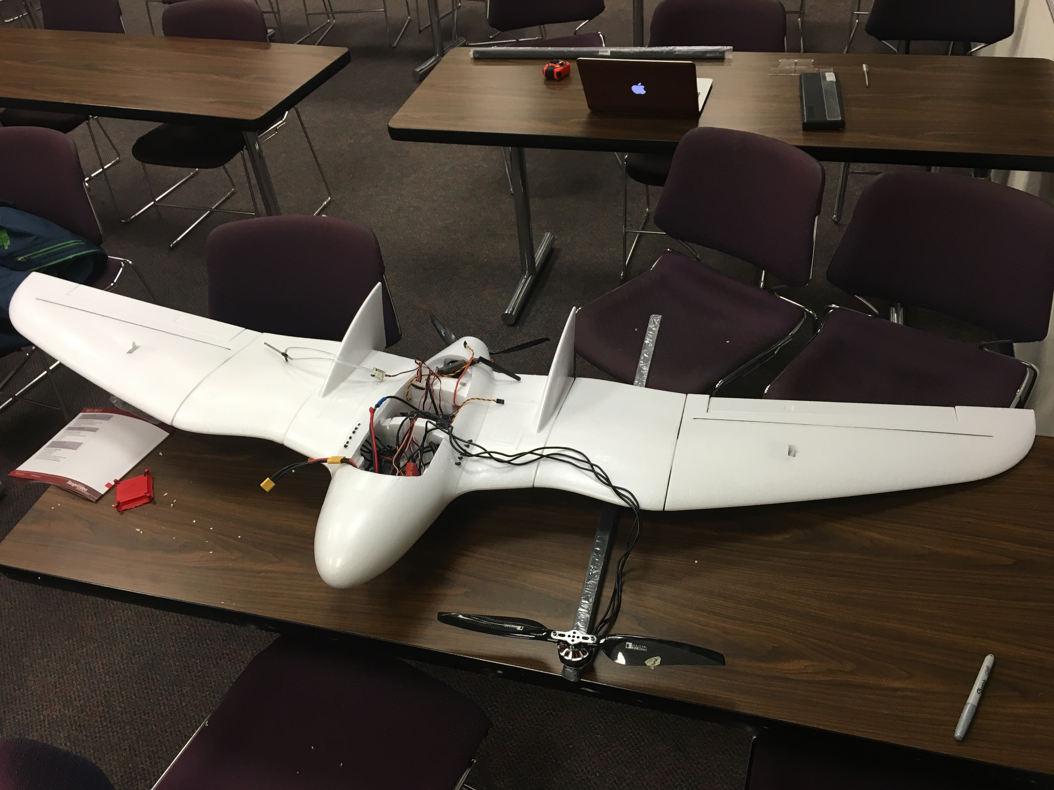

The motor booms were square 20x20x800mm carbon fiber tubes. We mounted them so their center was over the CG of the wing, that way the plane would balance out properly in flight. We laser cut acrylic mounting plates and passed the bolts straight through the wing. This was a very crude way of going about this, but it was simple and got the job done.
Next, I designed the motor mounts in Solidworks and printed them out. The first version didn’t have printed captured nut and bolt holes on the side so we had to drill those by hand, but the second rev, pictured to the right fixed this. This featured a counter bore for the cap screw and a captured nut insert to make all the hardware flush. Note, the way I designed this, the motor retaining bolts had to be installed before sliding the assembly onto the carbon fiber tubes.

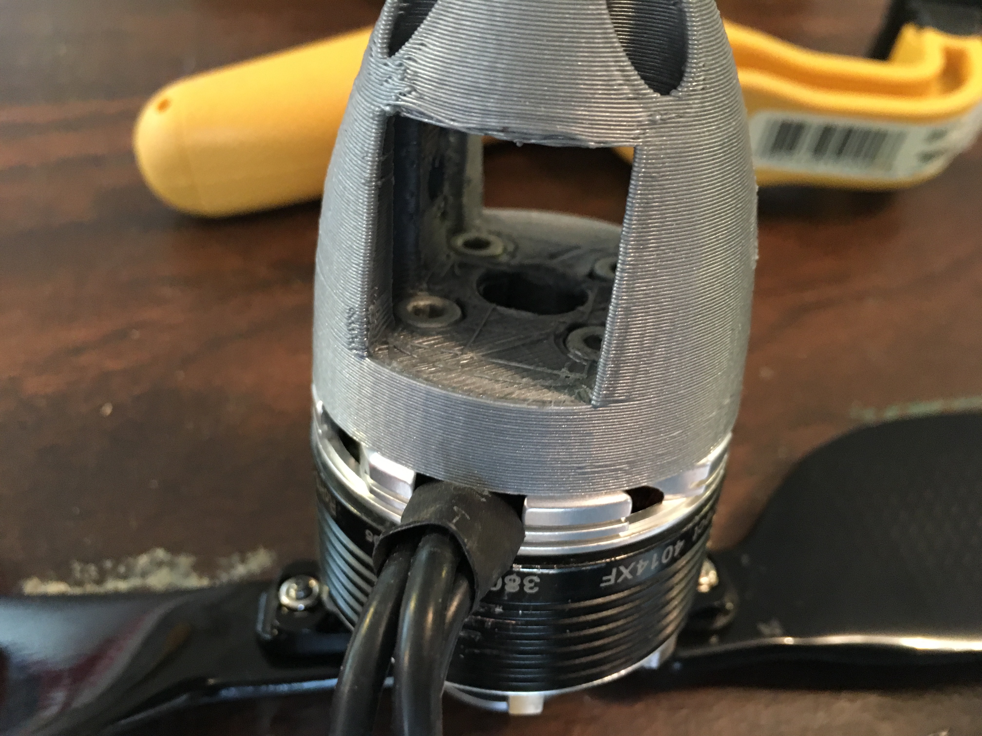
The motor retaining bolt holes had printed counter bores so the bolts sat flush, as pictured to the left, which allowed the carbon tube to pass through the square profile flush after the hardware was installed. The four holes in the top of the picture (bottom of part) were to allow access for a hex wrench to install the hardware. Finally, I gave the part a nice aerodynamic looking profile.
With the motors attached, the motor wires were routed through the boom and out near the center where they were connected with the ESC’s inside the fuselage. Now it was time to make sure all the motors were spinning in the correct direction and test fly this thing!

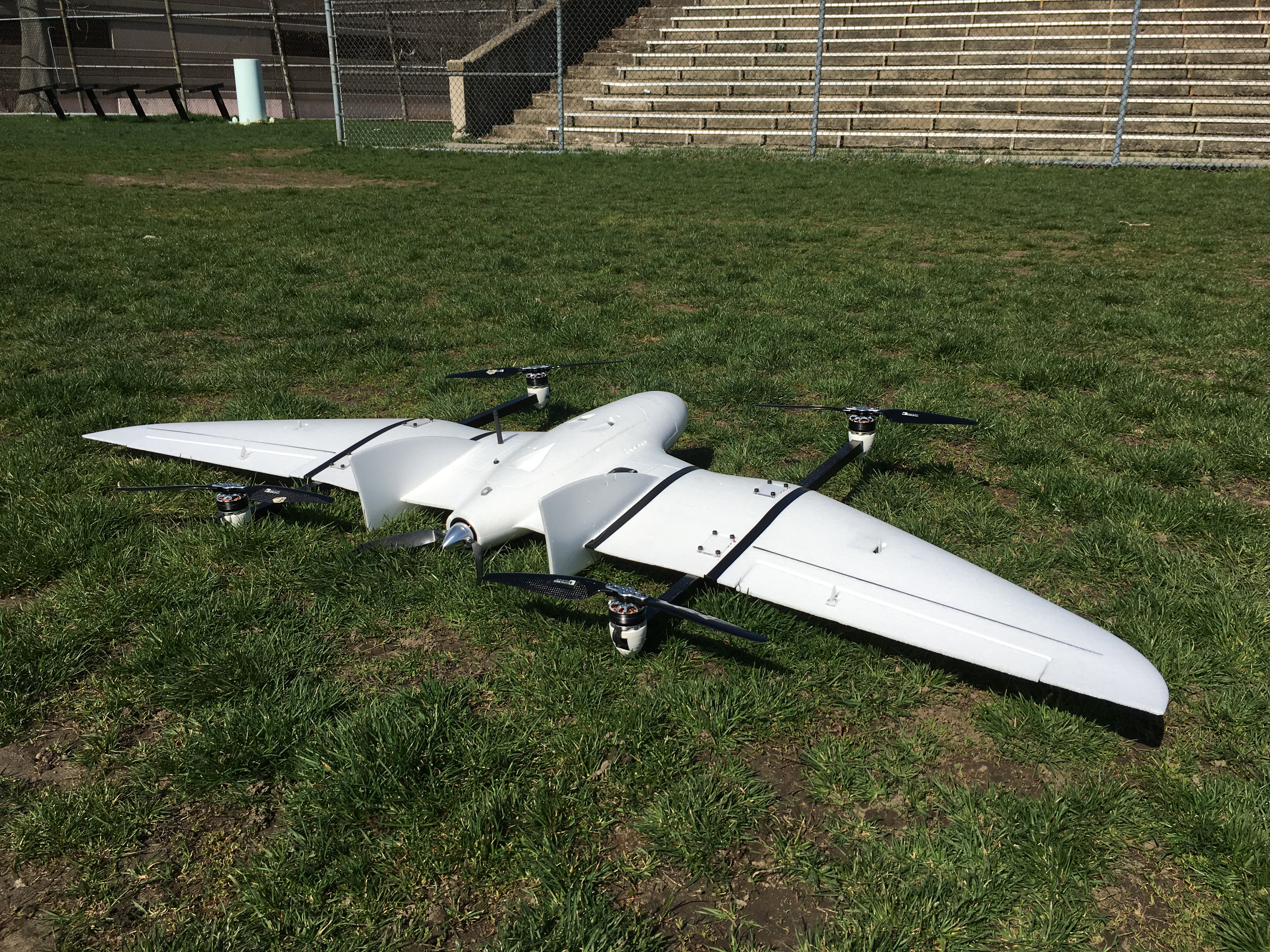
The motors were all spinning in the correct direction. We had a go for launch.
And success!! Initially the aircraft did not have enough yaw authority because with the long wings it had quite a bit of rotational inertia. I set the yaw parameter to the maximum in the ground control software (QGroundControl) and this seemed to fix the problem.
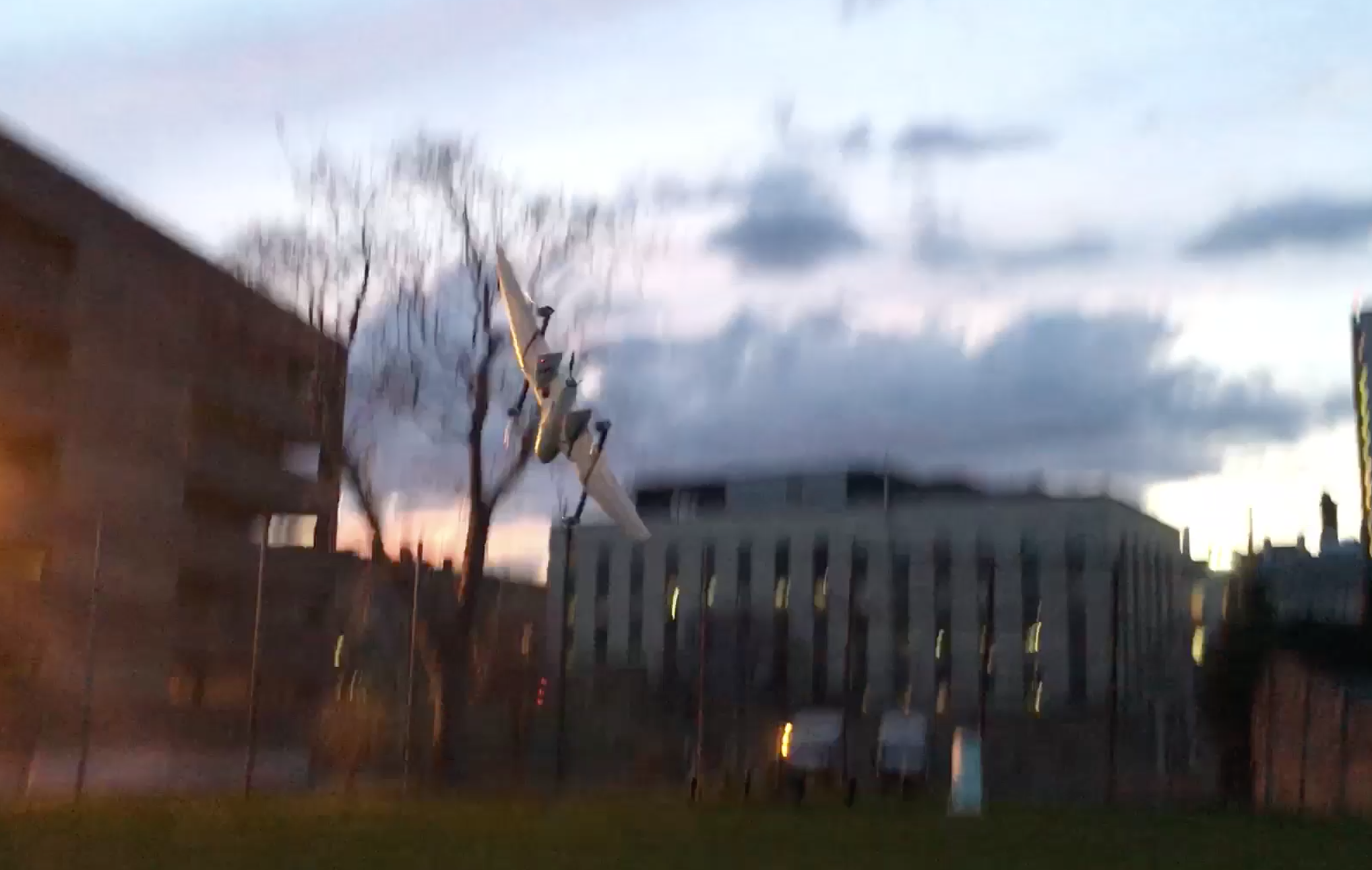
After the first handful of successful test hovers, the front left motor shutoff mid- flight which resulted in a rather hard landing. Luckily no damage was sustained. The equipment seemed fine so I thought this was just due to a loose connection.
The motor connections were all checked, and I designed new mount for the Pixhawk to make sure it was fixed securely to the airframe. Another test flight was performed and about 10 minutes into the flight, the front left motor failed again. This time smoke came from the motor and the windings were visibly fried. So, the cause of this problem was most likely a short in one of the windings.
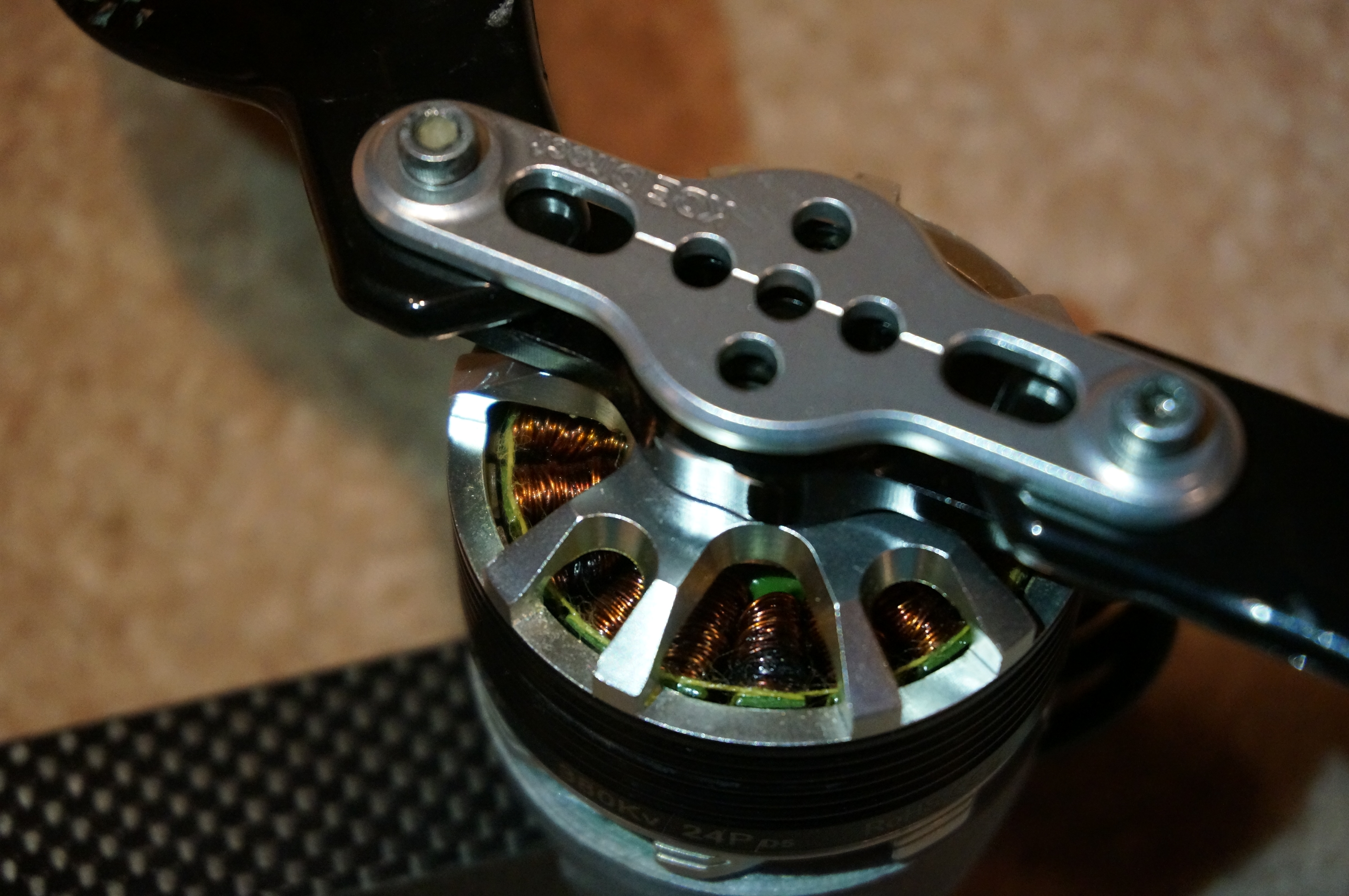
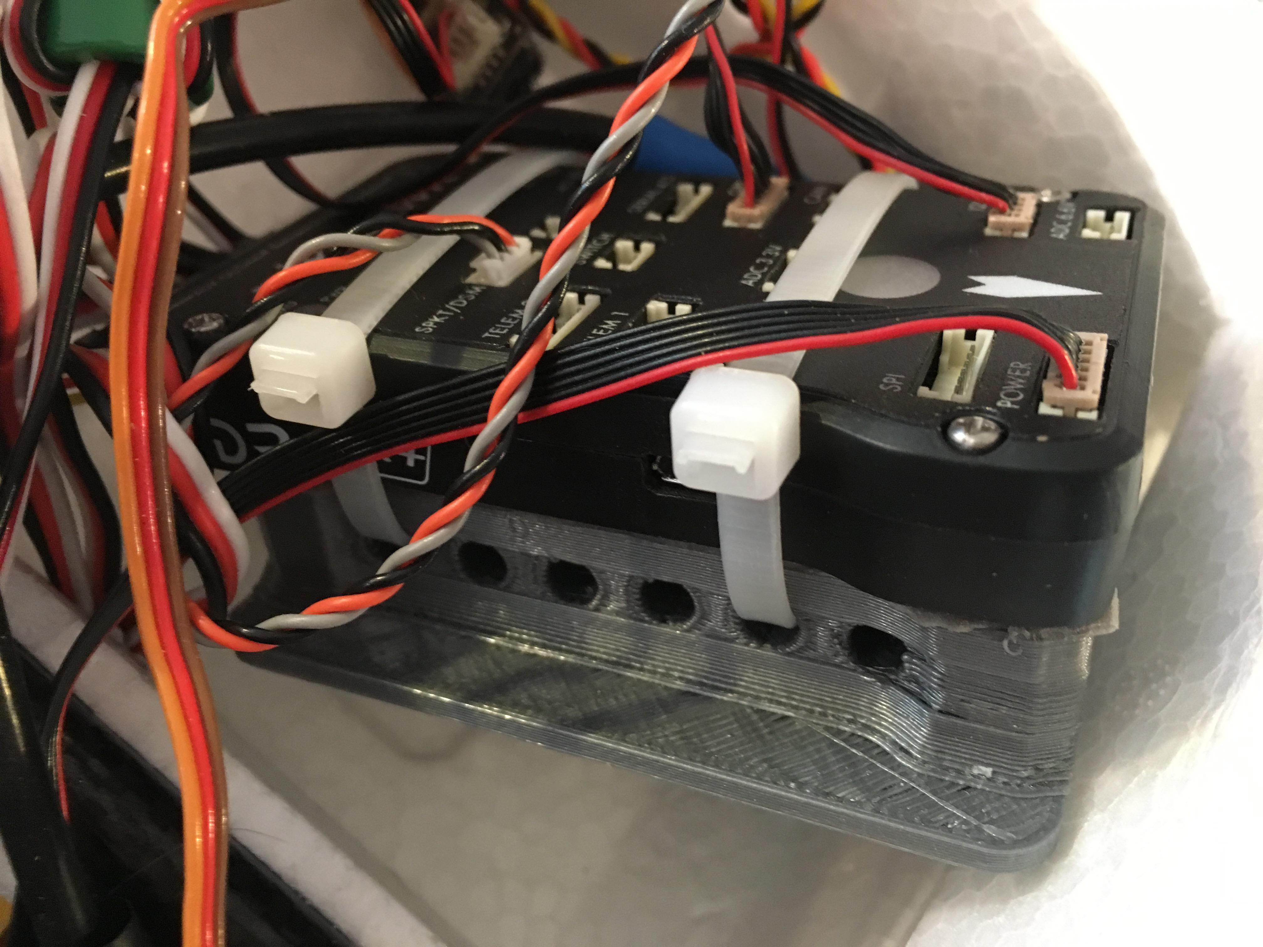
Fast forward to summer break. I replaced the burned motor with a new one and fixed any damage caused by the crash. After about 5 minutes into the first test flight the new motor failed the same way as the old one. This meant the cause of the problem must have been a faulty ESC. I would need to wait until the fall, however, to get a budget from AIAA for a new ESC because they were very expensive.
Fall semester came and we replaced the bad ESC with a new one and fixed the damage from the second crash. We also added a carbon fiber tube brace that joined the two front motor mounts. This helped prevent the motor mount arms from flexing during flight. Several hover tests were performed while closely monitoring the front left motor. The aircraft performed as expected and there were no problems with the motor so the issue was determined to be fixed. A cooling vent was also made to circulate fresh air over the ESCs to be ensure they were not over heating.
We were now ready to test forward flight. This meant completely shutting down the quadcopter and powering up the pusher motor. We had no way to test the aircraft in forward flight without doing a VTOL transition because it was too heavy to launch by hand. This meant we had to do our first VTOL transition attempt and forward flight attempt all in one go. All systems had to work perfectly. During forward flight all lift would be generated by the wing so it was important to have enough forward velocity when transiting. The PixHawk flight controller actually had systems to monitor the transition to ensure it went smoothly. This was a pitot tube airspeed sensor that monitored the airspeed during transition and would automatically abort the transition if a fast enough airspeed was not reached. This actually happened on the first attempt, and a parameter was adjusted in the firmware to give more pusher thrust during transition to reach a satisfactory airspeed.
This concluded the project for the semester. In the future I will be looking into doing topographic surveying using a process called photogrammetry with the aircraft. Basically you fly over geography taking overlapping 2D images and then there is software that uses triangulation between overlapping pixels to create a 3D mesh. It then textures the mesh with the stitched images to create a 3D map like Google Earth. This is a perfect application for a VTOL because it can take off in a small space and fly over a large area, unlike a convectional multirotor like what most people use. This can be useful in many industries such as agriculture, construction, or search and rescue to just name a few.


